Piggyback input boards
There was a comment earlier from Craig suggesting it would be useful to have input connectors on top of one another.
I have seen various types of such connectors interfacing to a single board. Most appear to be poorly made.
There are two alternatives as I see it:
1. Use 2 boards piggyback to get 2 rows
2. Turn the board 90 degress so that it is parallell to the back wall + find stuff that interfaces directly in that position.
Just my $.02
Petter
Cobra2 said:
Thanx...(I think)

I have already ordered my first set...but with this speed of development, and with more & new functions...I realize that this will not be THE control-system, but just one of THEM...
Arne K
I am wondering if the whole operation is more like a Ford that comes out with a model every 6 mo or a Mercedes that changes the design every 6 years. 😉
The scenario is one XLR output goes to one of the main speakers, the second output via an RCA goes to a subwoofer. The sub has an integral amp and crossover and I was going to passively use a High Pass filter on the XLR output
Yes, if you simply want the output to go to two speakers instead of 1 speaker. then you can take the output off of both boards.
I don't see a problem with that!
I am wondering if the whole operation is more like a Ford that comes out with a model every 6 mo or a Mercedes that changes the design every 6 years
Actually we are more like McDonalds, we have a new toy every couple of weeks

-Craig Beiferman
Craig,
Any further work on the SHM-spreadsheet that will show the function of all offered resistor sets?
Thanks, Robert
Any further work on the SHM-spreadsheet that will show the function of all offered resistor sets?
Thanks, Robert
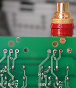
I tried a HiLine WBT connector. They require a couple of extra holes in the IS1, but will otherwise work just fine.
One of the holes requires a screw and securely fixes the RCA jack to the board, so no standoffs will be required. This particular jack is solderable. I translated the jack to the left for the inputs, creating a new hole for the left ground tab, using the center tap for the + and the other ground tab in the - hole. The Ground hole is empty, but one of the 0R SMT fellows will short the ground and - inputs. On the output, I shifted them one hole to the right. Spacing is now 30 mm between inputs, as before, but the output is spaced a little further, more to my liking, at 42 mm.
I'll post another image to follow.
Regards, Robert
Attachments
Do not want to sound all negative...
but the WBT has a larger/thicker body that requires a bigger hole...and nothing else will fit if you change your mind...
Arne K (Loves his Cardas...) 😉
but the WBT has a larger/thicker body that requires a bigger hole...and nothing else will fit if you change your mind...
Arne K (Loves his Cardas...) 😉
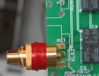
Yes, the hole is larger at approx 15/32 (0.47 or 12 mm), but plastic isolation inserts allow movement of slightly smaller units. I seem to recall that Cardas is 3/8 (0.375).
However, if you used WBT, why switch to anything else? 🙂
I've used Cardas for some time, but soldering to the ground ring is a pain while WBT has a few other options depending upon which model you choose. I like the idea of having an integral jack and board. Less flying leads is very nice. Also, the whole board profile is not so bad--about 1/2 inch. I'm stacking two boards on a rear panel of 75 mm external height; 3 could almost fit in this same space.
But in the end, just another option.
***
I made the hole for the display in the front of the chassis (stock is 0.090 aluminum). The best way seemed to use a router with a 3/8" bit (1/4" shaft) on a small PortaCable (meant for laminate trimming). After making a jig out of masonite I cut an opening 20 x 84 mm for the display, anchoring the jig to the front panel with #6 screws where the volume and selector knobs would eventually go. After the jig is removed, these #6 holes were enlarged with a 3/8" bit. The LED (standby) and IR sensor holes were placed 50 mm to the right of the selector knob, about 10 mm vertically apart from one another.
It went smoothly, but its important to use drilling oil while routing the aluminum.
Regards, Robert
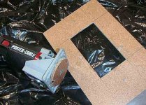
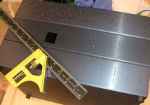
i was asked about the jig; below is picture. my son (14 and eager to help) and i fabricated a new base for router using a hole cutter (3" diameter, i think) which left a 70 mm diameter plug (r=35mm). exact dimensions are not important, but affect dimensions of jig.
this new base replaced the square base that came with router, using the old base to align mounting holes. square jig was made, reducing opening by about 4mm on each side to allow for router bit diameter. image of opening follows in next post.
this new base replaced the square base that came with router, using the old base to align mounting holes. square jig was made, reducing opening by about 4mm on each side to allow for router bit diameter. image of opening follows in next post.
Attachments
front panel of chassis for display is in middle. bottom tier is for power supply: maybe 2 or 3 (i havn't decided) for audio, one high current for 5VDC, and one set of RCA (probably rear surrounds). rear view on next post.
middle tier for display, another pair of IS1 boards for center and sub, and all APOX-SHM boards. upper tier will contain audio gain stages and provide more real estate for input/output connectors.
front panel will have a plate facade that encompasses all 3 tiers and has opening for display and knobs.
Attachments
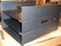
rear view. bottom right is RCA sets for 2 IS1 with leftmost column for outputs using WBT connectors. Left hole is for AC connector.
middle tier has more RCA-based IS1 connectors. left most AC hole is due to already being in chassis (i use these for power amplifiers too; anyone want some?)
upper tier will be for front left/right speakers with RC A inputs on right and XLR for fully balanced circuitry on left. the IS1 will mount directly to RCAs, but the XLR will use flying leads. An extra set of XLR outputs are available for passive high pass filtering.
regards, robert
Attachments
Dale & Craig,
Now that I'm putting together the monster preamp, I can see a circuit board change that would make life much easier for everyone: modular plugs (phone jacks).
Stacking boards makes it difficult to use terminal block screws as the top most board blocks easy access to the screws. Admittedly, you could choose a different style terminal block with easier access, but by switching to a modular plug, you can eliminate one terminal block and 2 sets of 3 pin I2C connectors.
If you replace the 5V terminal blocks and the two 3-pin I2C with two modular plug, connections will be easier. A single 4-lead telephone line will do, since the digital ground is present in both the terminal block and the I2C; it would only need to carry +5V-G-S-C. If you wanted more leads, using an RJ-45 would work equally well.
This modular plug could be present on the IR1 with 2 such plugs for daisy chaining on all other boards. Additionally, the crimping tools, plugs, wires and jacks are easy bought at various electronic stores like RadioShack. Connecting all the boards would be a breeze: plug and play.
Regards, Robert
Hi Robert,
Great idea. Just got in 50 IR1 boards, so we won't be changing in the near future... Does sound like it would be a good solution.
Dale
Great idea. Just got in 50 IR1 boards, so we won't be changing in the near future... Does sound like it would be a good solution.
Dale
modular jacks
Robert,
I did think about that, but was worried some of the relay boards would require too much +5v current to put through the modular jack?
-Craig
Robert,
I did think about that, but was worried some of the relay boards would require too much +5v current to put through the modular jack?
-Craig
The jacks are rated for 1A as I recall. If that is the case, then put 3 or 4 on the IR1 and recommend a limit of 4 (4x0.2A) daisy chained boards. I don't believe any board is listed for more than 200 mA.
If the terminal block is left on the IR1, this can be 'routing central' for the modular jacks.
If the terminal block is left on the IR1, this can be 'routing central' for the modular jacks.
Possible new feature?
Consider an Apox used as a volume control for a stereo set of speakers. This is what I will be using with a digital crossover.
When integrating this into a home theater setup, one has a problem. First of all, it is optimal to get the digital output from the surround sound processor (to the digital crossover or superior external DAC if available without digital crossover). What one could do to save money would be to use the surrround sound processor/amp as processor for everything AS WELL AS the DAC and power amps for all speakers but the front stereo set. Now we have a problem -- how does one synchronize volume settings?
Solution 1): Buy More Apox and (in my case) run everything through the Apox + loop back to surround sound amp (or better still use external power amps. Problem with this is number of channels available if going SHM as well as cost.
Solution 2 (and "feature request"): Intercept programming pulses internal to the home theater units (aka digital potentiometer or DAC volume programming) in Apox, decode, and use resulting bit patterns to set volume. Thus, Apox'es would "impersonate" a poorer volume control.
Solution 2 is very cool, but I am not yet sure how useful it would be. If the Apox attenuator boards themselves were able to impersonate, they would potentially open up a new market (home theater integration (into the amp, near the amp, or in subsequent stage [reads: in external power amp or pre-amp but still under HT amp control]) with FULL functionality integrating with existing display etc), and this is something that a DACT can NEVER do. Such a feature would of course require a certain amount of research and selection of desired device impersonations.
As a minimum, we should at least evaluate whether we need to have further "feature connectivity" on the Apox attenuator boards as well as the controller to enable impersonation scenarios or other future software wizardry.
The above discussion describes an integration scenario with HT, but could easily be used with stereo setup, reducing cost of implementation significantly (build into CD player for example -- you save box, Apox controller and retain FULL device cabability)
I have certainly not thought about all the challenges that such a scheme would represent, an not even if this is a "feature request" that is of general interest or even a project worth pursuing. However, I hope others would agree this is would be cool!
Petter
Re: manual updates
Where exactly are those manuals? I can't find them.
I received my kit yesterday. Thanks.
dipchip said:The APOX-2, APOX-IS1, and APOX-IR1 assembly instructions
have all been updated with a little more info added, and a few mistakes have been fixed. (Such as LED orientation)
-Craig
Apox Web Page
Where exactly are those manuals? I can't find them.
I received my kit yesterday. Thanks.
Drool
I received all my Apox stuff today including 6 SHM boards (yeah, I know you all hate me for having this cool stuff to play with!)
The layout, particularly on the SHM was very very nice 🙂
Nice thick boards -- a nice surprise which I don't believe has been mentioned before. Dale could have gone with el-cheapo's but obviously devided not to.
Extremely professionally packaged.
And I was very positively surprised by how small everything was. This will of course make it easier to integrate into other systems.
WOW!
Petter
Yes, those boards have very nice feel and look extremally good. A big step up from the first board.😉 (I got both boards to compare).
I was wondering if those encoders are available in non-detented type as well?
I was wondering if those encoders are available in non-detented type as well?
- Status
- Not open for further replies.