Re: APOX-SHM update.
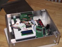
Actually, below is my project was for last semester, and I used my pic dev board, along with a vfd, different optical encoder and a pga2310 board that I made, and it worked great. I was going to get my own pcb made for the front panel, but yours looked so good that I couldn't resist just using it instead, converting my pga2310 board over to i2c, and I would be done.
--
Brian
dipchip said:BrianGT,
Awesome work! I can't wait to see the boards stuffed in the box. But make sure you finish your homework. 😀
Or, are you using the Apox kit as a school project?
Actually, below is my project was for last semester, and I used my pic dev board, along with a vfd, different optical encoder and a pga2310 board that I made, and it worked great. I was going to get my own pcb made for the front panel, but yours looked so good that I couldn't resist just using it instead, converting my pga2310 board over to i2c, and I would be done.
--
Brian
Attachments
JasonL said:Brian you should take a pic of your bare boards and post them on your pic gallery as im there every day looking and druling over your stuff and creations.
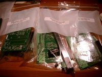
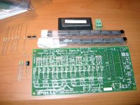
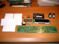
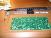
Here is a better picture of all the boards. I have the 3 - IR1 kits done now, which will do it for now. The top one is rev3, which I will mount the encoders with cables to get the spacing that I want, the second one is the older revision pcb, which will be mounted with the encoders close together, and the 3rd one is the rev3 board with the encoders in the proper location, which I am thinking might be too far apart for my tastes, but I am going to make a wider chassis for this one. The two bare boards are an IR1 and an APOX2 board.
I need to start working on my i2c interface chip for my pga2310 setup. I am trying to use one of those 8-pin pic12f675 to do this task, as I picked up the new PICKIT1 FLASH starter kit from Microchip. Highly recommended. $35 from digikey for the kit, which includes a C compiler and a USB programmer.
--
Brian
Attachments

The missing ULN2803A's were posted today. I apologize for any delays that this causes in your builds.
harvardian said:The missing ULN2803A's were posted today. I apologize for any delays that this causes in your builds.
Dale how was my order shipped?
Anthony
Anthony,
I believe that your order went out USPS Air Mail. I would assume that you have not received it yet. It should arrive in the next day or two. Your missing parts were also posted today via USPS.
Dale
I believe that your order went out USPS Air Mail. I would assume that you have not received it yet. It should arrive in the next day or two. Your missing parts were also posted today via USPS.
Dale
harvardian said:Anthony,
I believe that your order went out USPS Air Mail. I would assume that you have not received it yet. It should arrive in the next day or two. Your missing parts were also posted today via USPS.
Dale
Arrr Billy thar be kits here.....
🙂
Anthony
APOX-IR1 Standby Transistor
Hi Dale and Craig,
I think I mentioned this before... I want to turn ON/OFF my amp using relays (one for each power supply in my dual mono amp) that will be driven by 5V connected to the output of the standby transistor on the APOX-IR1 (opto-isolated).
Each 5V relay needs about 200mA of current, so thats 400mA for both that the standy transistor needs to sink.
I looked at the specs of the TIL197, and it is rated for a max power dissipation of 150mW on the output. I don't think it can handle these relays, so is there a drop-in part that can handle more current?
Thanks for your help,
Vinnie
Vinnie,
I don't know of any opto-isolator that can handle that much current in a 4 pin dip package.
You might want to interface the current opto to a much smaller relay or a MOSFET which would then control the current to your big relays.
Does anyone want a small PCB to cycle some A.C. power on and off?
-Craig
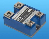
Ive used solid state relays similar to this for quick-n-easy ttl control of AC lines.
http://www.mpja.com/productview.asp?product=11373+RL
http://www.mpja.com/productview.asp?product=11373+RL
Attachments
Re small PCB for power cycling:
There are manufacturers who make good money selling soft start circuits. If you do go into the "small power cycling PCB" business, consider making it that way. One good example is LC Audio who make a turn-on delay with relay bypass (manual power switch) which seems to sell like hot cake. http://www.lcaudio.dk/tilb.htm is based on what looks like a Fairchild(?) P02AB CD40608CM but then again a transistor, cap a couple of diodes do the same thing.
The circuit should be an on-off relay with a thermistor to limit in-rush. Then after a few seconds, the whole shebang should be bypassed by another relay (and depending on configuration the main relay be switched off but this is not critical)
Thus, two optical signals might be even better. Analog (or better still digital) delay circuits are pretty easy to make though. I have seen plenty such circuits (and built a few too ....)
Petter
harvardian said:The missing ULN2803A's were posted today. I apologize for any delays that this causes in your builds.
I just received my kits today, less the ULN2803A's. No problem, there is no hurry, as I will work on it this weekend. Here are some pictures:😎
Attachments
Henry,
Awesome, I was worried about the long distance shipment to Hong Kong. I can't wait to see what your final system looks like.
Good luck in your construction and thanks for the photos!
Vinnie,
For the price of the SSR, its probably easier to buy those.
then to rig up a little circuit board. (maybe? )
)
-Craig Beiferman
Awesome, I was worried about the long distance shipment to Hong Kong. I can't wait to see what your final system looks like.
Good luck in your construction and thanks for the photos!
Vinnie,
For the price of the SSR, its probably easier to buy those.
then to rig up a little circuit board. (maybe?
)-Craig Beiferman
Hi Craig,
I will use the opto-darlington to power a smaller 5V relay that uses very little current, and then use the smaller relay to provide 5V to the higher current 5V relays that I will use to power my amp. This is the easiest way I think.
Thanks for your help!
Vinnie
I will use the opto-darlington to power a smaller 5V relay that uses very little current, and then use the smaller relay to provide 5V to the higher current 5V relays that I will use to power my amp. This is the easiest way I think.
Thanks for your help!
Vinnie
I've been getting all funky with some Javascript's on the web page.
Can people tell me if they like the improvements, or better yet, if they even work on your system at all.
(You should see a tabbed view, and pictures cycling)
Now, its time to go see the "Matrix Reloaded"!
I can hardly wait! 😀
😀
Thanks,
Craig Beiferman
DipChip Electronics APOX web page
Can people tell me if they like the improvements, or better yet, if they even work on your system at all.
(You should see a tabbed view, and pictures cycling)
Now, its time to go see the "Matrix Reloaded"!
I can hardly wait!
😀Thanks,
Craig Beiferman
DipChip Electronics APOX web page
dipchip said:Can people tell me if they like the improvements, or better yet, if they even work on your system at all.
Thanks,
Craig Beiferman
DipChip Electronics APOX web page
Nice work Craig! it is looking better and more organized.
Now you just need to work out your color scheme 😀
Something about the black background and green text
really doesn't click to my eyes

Oh wait, you just wanted to know if we like your improvements
and if they work, not my "constructive" criticizm again 😉
Ps: did you get those APOX-SHM boards in yet?
-Vinnie
APOX-IR1 Assembly
I have a couple of question arise during assembly, if someone could help me:
1. R4,25 listed as 10M, but I measured 1M (I never remember the colors, so I measure them). Is this an update or mistake?. Should I use 1M or dig out 10M from my stock; or does 1 and 10M have no difference.
2. U4 is listed as F2166-ND on the assembly sheet, is this the SP721AP I have left over?
3. OK, I'm a dummy: I saw in DIY forum Enc1 and 2 are different: one is 16 step (sel; 61C22), the other 32 (vol; 61C11). But which one goes left of display as you face the display, the selector?
Thanks, Robert
PS To Craig and Dale: you guys are incredible. The kits are really exciting. I cannot wait to get all assembled for a surround setup.
- Status
- Not open for further replies.