Missing parts
Hi Guys,
I think that I made a small error in almost everyone's kit. I was waiting for static foam and when it arrived, I was supposed to put in all of the semiconductors. Unfortunately, me thinks that I forgot all of the ULN2803A's.
Please check your kits and tell me the bad news via an email to support@dipchipelec.com
I will post these tomorrow!!!
Best Regards,
Dale
Dale said:
Good help is hard to find nowadays!


Just kidding Dale!
I think that I made a small error
Good help is hard to find nowadays!
Just kidding Dale!
Member
Joined 2002
Brian you should take a pic of your bare boards and post them on your pic gallery as im there every day looking and druling over your stuff and creations.
Forgive my ignorance,
But how many steps will these volume control boards allow?
The thread is just too long for me to read through.
Yuval.
But how many steps will these volume control boards allow?
The thread is just too long for me to read through.
Yuval.
BenY said:Forgive my ignorance,
But how many steps will these volume control boards allow?
The thread is just too long for me to read through.
Yuval.
Less than too many and more than enough!
1024 I think for the APOX 1, not sure on the rest.
Anthony
Coulomb said:
1024 I think for the APOX 1, not sure on the rest.
1020 according to dipchipelec.com, but we've been tossing around so many proposed changes to the switching logic, that it could be anything. 🙂
Unfortunately my board is currently a 0 position attenuator with no ULN2803A's. 🙂
BTW, nice packaging; nothing fancy, but very effective. Tossing in a schematic and a printed picture of a finished board for each kit may save you some confused calls or e-mails.
Also, before you guys freak at the scratches on your LCD display, note that there is a protective film over it.
Sheldon
JasonL said:Brian you should take a pic of your bare boards and post them on your pic gallery as im there every day looking and druling over your stuff and creations.
My gallery is gone as of this week

But it will be back. I have my own 400mb webhosting account, but I can't find a domain name that I like to point at it. It currently is just http://brian.prohosting.com which is dull and boring.
Here are some pictures that I took a second ago for you. I have one IR1 board working, but I haven't soldered the display or encoders on it yet, as I need to configure the encoders differently for my chassis (closer together for my 12" wide chassis) and I want to socket the display so that it can easily be removed.
picture 1 of the working board:
An externally hosted image should be here but it was not working when we last tested it.
(note that I am using a solder spool to hold the display contacts in place 🙂 )
picture 2 of all the boards
An externally hosted image should be here but it was not working when we last tested it.
(well.. I have 2 more IR1 boards not shown here)
The images are a little crappy, since my camera battery is almost dead, so I hurried them, and then I used mspaint to resize the images instead of the gallery software.
For those putting the IR1 board together, here are a few suggestions:
1.) There is no R14. I spent quite a bit of time looking for it in 2 of my IR1 kits, but alas, it wasn't there. I ran it without it, and the backlight was not lighting up, but I could still read it. I noticed that it said 0 ohms on the BOM, and put a short circuit jumper there, and it worked.
2.) Check polarities on the Tantalum capacitors. I didn't, and had to pull 3 of them out and reverse them, which took a large chunk of my time, since I reversed the ones with the smallest pads. The pads are barely visible, and the solder is almost impossible to suck out of the plated through holes. Double check this, then triple check this, and then solder them in.
3.) Double check the polarities of the dip chips. I had one backwards when I first powered it up, and it overloaded my bench power supply, but I reversed it and it worked perfectly.
4.) Take your time and enjoy yourself. I took my time, talking to my friend who just finished up his first 2 gainclone channels, taking turns with the iron.
Thanks Dale and Craig for making this project a reality!
--
Brian
Member
Joined 2002
number of volume control steps
Sorry, I need to update the web site.
The maximum number of possible steps with the APOX-1 is 1023 steps, but I linearized the steps, and put the data in a lookup table, so the current number of steps is actually 255 for the APOX-1, But after listening, 255 is more than enough.
The APOX-2 is 23 steps with 1 mute step.
P.S. We will ship the ULN2803A's as soon as possible.
-Craig
1020 according to dipchipelec.com, but we've been tossing around so many proposed changes to the switching logic, that it could be anything.
Sorry, I need to update the web site.
The maximum number of possible steps with the APOX-1 is 1023 steps, but I linearized the steps, and put the data in a lookup table, so the current number of steps is actually 255 for the APOX-1, But after listening, 255 is more than enough.
The APOX-2 is 23 steps with 1 mute step.
P.S. We will ship the ULN2803A's as soon as possible.
-Craig
BrianGT,
Wow, you got your board running pretty fast.
I'm happy to see that the firmware is running.
P.S. to all builders who are putting the encoders and the LCD's on a ribbon cable. Be very careful about the pinout.
For a ribbon cable the header would need to be on the back of the board.
Also please double check your kits part lists. Make sure everything on the list has been crossed off. Inform us ASAP of any missing parts.
Also for the I2C hookups, There are three signals, GND,SCL,SDA
Each board has an input and an output I2C connection.
These two connections are hardwired together and are identical.
You should daisy chain the I2C from 1 board to another.
each pin connects to its matching label on the other board.
For instance a typical connection might be:
APOX-IR1(GND) to APOX-1(GND) to APOX-IS(GND)
APOX-IR1(SCL) to APOX-1(SCL) to APOX-IS(SCL)
APOX-IR1(SDA) to APOX-1(SDA) to APOX-IS(SDA)
Thanks,
Craig Beiferman
Help!
Did someone offer to writeup instructions on how to build
an APOX kit. If you did, then I accept!
Dale and I are struggling to update the documentation, update the web sites, and release the new boards. Any help would greatly be appreciated.
I'll try to update the FAQ, as new questions come in.
Thanks,
-Craig Beiferman
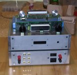
I now have 2 working IR1 boards. Here they are with my chassis, which haven't been brushed and anodized yet. The bottom one is mine, and the top one is my friend's. I am going to have the machine shop at school cut some new front panels for the chassis next week for the larger display and dual encoders.
--
Brian
--
Brian
Attachments
Member
Joined 2002
That is some nice work man. Hey where do you go to school. How do you afford your projects and do school. ?
Brian,
I am glad to see that someone else bought the same crappy set of pliers cutters and needle nose at sears. I am down to my third set, the cutters have a tendency to punt when put under too much pressure. Gotta love the lifetime warranty! 😉
A question:
is it me or you mounted the encoders on the wrong side? Did you get an earlier version of the board?
APOX-SHM update.
BrianGT,
Awesome work! I can't wait to see the boards stuffed in the box. But make sure you finish your homework. 😀
Or, are you using the Apox kit as a school project?
APOX-SHM people rejoice,
Dale has put in an order for the APOX-SHM boards.
hopefully we'll be testing this board next week. Dale will finish the
pricing soon.
I have been working hard in laying out the ALW/Jung regulators.
I am trying to make a 3 terminal 7815/7915 type replacement.
It looks really good so far. 😛 it has the on-board pre-regulators for some awesome performance (I Hope).
I wanted to finish the Jungs before I finsihed the APOX-3,
because I wanted to make sure that the Jungs will fit easily on the board.
Thanks everyone,
Craig Beiferman
JasonL said:That is some nice work man. Hey where do you go to school. How do you afford your projects and do school. ?
There is a great thing called Co-oping, where you work you work for a semester, take classes the next semester, then work the next semester, and so forth, where I can get cash to pay for my projects, and get some work experience for my resume when I graduate.
I go to school at Georgia Tech.
--
Brian
grataku said:Brian,
I am glad to see that someone else bought the same crappy set of pliers cutters and needle nose at sears. I am down to my third set, the cutters have a tendency to punt when put under too much pressure. Gotta love the lifetime warranty! 😉
A question:
is it me or you mounted the encoders on the wrong side? Did you get an earlier version of the board?
As for the pliers, I have a two broken ones here on my table, which I need to take back to get replacements. They are actually decent quality pliers and cutters for the money. I picked up a bunch during the christmas sales. The warrenty is great.
As for the backwards encoders, one of the pcbs is the older revision with the backwards encoders, which will work perfect. As for the other one, I am wiring the encoders to the board, running the wires from the back side of the pcb, around to the front. The two chassis are identical in exterior dimensions, but the top ones has 1" square stock in the corners, making it 9" wide, which is a bit too small for the pcb to mount in there. The bottom chassis uses 3/4" square stock for the corners, so it fits perfectly on the front of the chassis.
--
Brian
- Status
- Not open for further replies.