Member
Joined 2002
A metal Cutting question. I have a small table saw that my dad gave me he has a Larg grinding wheel on it. Can i use this setup to cut alumium.
And is it safe to do so. ?
And is it safe to do so. ?
I think it depends on the grinding wheel. I remember years ago my dad (a machinist) explaining to me that many grinding wheels aren’t formulated to work with aluminum. The abrasives don’t where off properly and instead become impregnated with aluminum. This can result in catastrophic fracturing of the grinding wheel. I'm told that grinding wheel explosions are quite nasty.
Perhaps this was something he told me to keep me from screwing up his bench grinder. But he really wasn’t prone to anything other than the straight truth.
If you cant positively identify the blade and what metals it is rated for, hang it on the wall and get a new blade. I would recommend checking the Peter Daniels thread on tools and techniques. I seem to recall that he talks about the blades that he uses on that nifty little panel saw he has.
-Dave
Da5id4Vz said:Brian, that’s one fine looking chassis! Are there dados cut to hold the top plate in place? I was wondering if it might tend to resonate or buzz if its snug fit or held in place by gravity.
Do you plan on applying Dynamat to the back of the Proto-board?
The top sits on the 4 - 1" solid square stock pieces, and is held in very snug with the front and back. The back is easily removable with thumbscrews, which makes it easy to remove the top. It is not resonating at all. Once I finish the case, I might put some sort of material inbetween the surfaces, but for now, I will probably have to take the whole thing apart to get the pieces cleaned up and anodized.
For the insides, this is far from finished. I am going to make a pcb to hold all of the components, rather then use the protoboard that I am using now 🙂 I am just in the prototyping process. This is for my final project for one of my school classes this semester, so once I get the checkoff for it, I will change a few things, mainly not using SPI, and using i2c. SPI was the requirement for the project, and it is not easy to use both.
--
Brian
JasonL said:A metal Cutting question. I have a small table saw that my dad gave me he has a Larg grinding wheel on it. Can i use this setup to cut alumium.
And is it safe to do so. ?
I don't know how well the cutting blade would work on aluminum. I am guessing that since aluminum is soft, it might get stuck to the cutting wheel. This is what happened to my small dremel tool grinding wheels.
If it does work, I don't think that it would have anywhere near the accuracy and smoothness of cuts as the non-ferrous blades do.
--
Brian
Attachments

An abrasive blade is not the bda method of cutting aluminum. (that's Brian Donaldson Approved) If you want to cut aluminum with a table saw, use the non ferrous, triple chip, negative rake carbide tip blade shown the thread above. I use a DeWalt 12" model DW3229 in a 12 compound miter saw and a simular non ferroius blade in a skill saw for long cuts.
An abrasive blade may eventually melt its way through aluminum, but a hachet would make a cleaner cut. (joke) The blade will load up with molten peices of aluminum and leave you with something you'll need to recut to make any use of where a skillsaw with a $30.00 blade used with a straight edge as a guide will leave a near mill finished square and straight edge. At least that's been my experience with 1/4" plate that I cut for my chassis. And I'm sure a table saw with the right blade would do at least as good much more quickly and easily.
An abrasive blade may eventually melt its way through aluminum, but a hachet would make a cleaner cut. (joke) The blade will load up with molten peices of aluminum and leave you with something you'll need to recut to make any use of where a skillsaw with a $30.00 blade used with a straight edge as a guide will leave a near mill finished square and straight edge. At least that's been my experience with 1/4" plate that I cut for my chassis. And I'm sure a table saw with the right blade would do at least as good much more quickly and easily.
APOX/Firmware Update
Last Friday, Dale gave me his .HEX file for the APOX-IR firmware.
He told me when you can download this .HEX file over RS-232
to the board you will see the LCD display a message.
Well, I love challenges, So I began a quest to write an RS-232 based bootloader.
(I had already written a USB based bootloader, so I figured I'd
have no problems)
Well after struggling for 3 days on my RS-232 bootloader.
It finally worked. Man what a pain that was!
I was using Visual C++, so I thought I could use MSCOMM
(a simple OCX file) to control the COM ports. Well after finally getting the communications working properly. I found out that the MSCOMM does not transmit the hex byte 0x00. So a few bytes of from the blocks of flash memory were not getting transferred. (It think it had something to do with VARIANTS and CStrings conversion.)
Anyway, I got rid of MSCOMM, and used the normal CreateFile, Read,Open,Write, and now it all seems to work fine.
The LCD finally jumped into action. Yee Haw!
I built most of the APOX-IR1 board. But I was missing a few parts that Dale didn't leave me before he left for vacation.
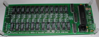
I also received the APOX-2 Board today. It looks pretty nice (if I do say so myself) 😉 I'll try to build that up tonight.
-Craig
Last Friday, Dale gave me his .HEX file for the APOX-IR firmware.
He told me when you can download this .HEX file over RS-232
to the board you will see the LCD display a message.
Well, I love challenges, So I began a quest to write an RS-232 based bootloader.
(I had already written a USB based bootloader, so I figured I'd
have no problems)
Well after struggling for 3 days on my RS-232 bootloader.
It finally worked. Man what a pain that was!
I was using Visual C++, so I thought I could use MSCOMM
(a simple OCX file) to control the COM ports. Well after finally getting the communications working properly. I found out that the MSCOMM does not transmit the hex byte 0x00. So a few bytes of from the blocks of flash memory were not getting transferred. (It think it had something to do with VARIANTS and CStrings conversion.)
Anyway, I got rid of MSCOMM, and used the normal CreateFile, Read,Open,Write, and now it all seems to work fine.
The LCD finally jumped into action. Yee Haw!
I built most of the APOX-IR1 board. But I was missing a few parts that Dale didn't leave me before he left for vacation.
I also received the APOX-2 Board today. It looks pretty nice (if I do say so myself) 😉 I'll try to build that up tonight.
-Craig
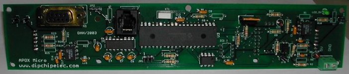
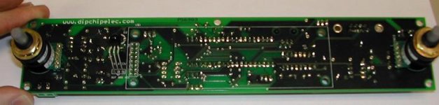
Oh yeah, The LCD would mount on the back of the board
of the previous picture. I forgot to take a picture with the LCD on.
-Craig
of the previous picture. I forgot to take a picture with the LCD on.
-Craig
What do we think?
We'll I think we may be looking at a new standard in the DIY audio world.
This has me already thinking about adaptations for multi-room audio distribution and control.
When do we start talking about the crossbar switch?
We'll I think we may be looking at a new standard in the DIY audio world.
This has me already thinking about adaptations for multi-room audio distribution and control.
When do we start talking about the crossbar switch?


APOX-IS1 boards arrived today
The APOX-IS1 (Input Select Boards) arrived today.
Hopefully I can build them up after work, and possibly post pics by 6:30.
Hee hee. 🙂
Things are really starting to come together!
Hopefully we can get all of these boards talking in the very near future.
P.S. Jam, what does your picture mean?
-Craig
The APOX-IS1 (Input Select Boards) arrived today.
Hopefully I can build them up after work, and possibly post pics by 6:30.
Hee hee. 🙂
Things are really starting to come together!
Hopefully we can get all of these boards talking in the very near future.
P.S. Jam, what does your picture mean?
-Craig
IR receiver
When I look at your IR receiver, it strikes me that you might end up with the same problem I had (if I can make the unit out correctly)
The problem was that the unit was just too sensitive (causing all kinds of strange problems), and so I have standardized on metal capped units with relatively small aperture (the metal appears to be a very effective light shield 🙂 ha ha) and so all my problems disappeared.
Petter
IR sensitivity
Peter,
Did you use a normal IR PhotoDiode.
Or did you use one with built in AGC, BPF, and demodulator
to only respond to the desired carrier frequency.
Like the Panasonic PNA4611M. (Im not sure which model Dale actually choose)
I once used a normal photodiode, and did indeed had saturation problems like you described when the detector was exposed to sunlight. But the demodulated versions are pretty immune to most ambient light from windows.
-Craig Beiferman
I'll chime in.
I have picked the Vishay TSOP4840 with built-in filter/demodulator. You are free to use any suitable model including the Panasonic ones that have optional metal shields. I think that any frequency from 38-40KHz would work fine. I chose the 4840 since Vishay listed it as compatible with the most formats including the Sony and RC5 that I support in software.
You can also put a recommended filter in front of the detector. If you go to the Vishay site, they have an application note on various types/colors of plastic that offer the best filtering of stray light, but let through the IR wavelengths.
Again, since I use a modulated/demodulated system, ambient light should not be a real problem.
- Status
- Not open for further replies.