I haven't been following this too closely, but could a person order only one new input board and use it for just two inputs, but left and right channels?
If you could figure out a way to configure it either as 4 left or right channels, or 2 left AND right channels, that would be quite appealing. I just use a CD player and a tuner. so I would only need one board. This isn't essential, the savings wouldn't be too much , but it would in fact tbe cheaper, AND smaller for those of us with lesser needs.
If you could figure out a way to configure it either as 4 left or right channels, or 2 left AND right channels, that would be quite appealing. I just use a CD player and a tuner. so I would only need one board. This isn't essential, the savings wouldn't be too much , but it would in fact tbe cheaper, AND smaller for those of us with lesser needs.
Dale and Craig,
How about mirror imageing the input boards (left and right) and maybe the volume control boards?
Keep up the good work.
Regards,
Jam
How about mirror imageing the input boards (left and right) and maybe the volume control boards?
Keep up the good work.
Regards,
Jam
APOX Status Update
Hi guys,
As some of you know, Dale and I have scrapped the first remote board and input/volume control board for the new I2C scheme.
After some hard work the new APOX-IR1, APOX-2, and APOX-IS1 layouts have been completed and all boards have been ordered in prototype quantity. (3 APOX-IR1's, 3 APOX-2's, and 4 APOX-IS1's)
(My mouse button finger still hurts!)
I sent the new APOX-IS1 board layout to Dale.
He got so excited, he ordered the boards immediately.
The new layout looks much better. For the loading resistors on the input select lines. I opted to use SMT 1206 resistors. This allowed the board layout to be much much cleaner. Also the input lines are now spread much further apart, and should induce little crosstalk. 50mm traces are used for all audio signals.
I've found 1206 resistors to be pretty simple to solder, so I hope no one has a problem with that.
Variac, The new APOX-IS1 only has 1 output connector so it couldn't do both left and right. 🙁
I'll try to get the new APOX-IS1 schematics posted today!
(but its basically half the old schematic)
I'll also begin modifying the APOX-1 schematics per petter's request to see if people like that.
-Craig Beiferman
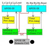
Overall system diagram
Hi guys,
Just so everyone understands the way the boards are laid out.
Here is a small system diagram.
Jam, I know the boards are not symmetrical mirrors, but the Left and the Right are completely seperated, so it is a good first step?
Also note that if you are using only single ended signals:
The APOX-2 has the two volume controls with seperated grounds. So you actually only need 1 volume control board.
I hope this helps,
Craig
Attachments
Looking Good!
Craig,
It gets my vote. I plan to isolate both the right and left channel as much as possible. Only one small request if possible to leave a small space between the output connector and the inputs (cosmetics). 😉
Regards,
Jam
Craig,
It gets my vote. I plan to isolate both the right and left channel as much as possible. Only one small request if possible to leave a small space between the output connector and the inputs (cosmetics). 😉
Regards,
Jam
May I suggest that you consider putting space or standardized connection of some sort to enable people to make their own gain boards?
One such should be before volume control, the other after. That way people can truly leverage their DIY skills in the gain stages 🙂
Also, may I suggest that you consider making the case size large enough to accommodate extra stuff such as gain stages, more power supply stuff etc.?
I am very impressed with the work that you guys are doing, not to mention the speed at which you are evolving. This has surely been an inspiration to us all here at DIY Audio.
Petter
Apox 1 volume switching scheme?
Could you please outline how you are planning to switch the Apox 1 relays? Is it simple binary or are you using a different modulation scheme?
Petter
Could you please outline how you are planning to switch the Apox 1 relays? Is it simple binary or are you using a different modulation scheme?
Petter
Jam,
I thought about moving the output connector over, but was worried about the final size of the enclosure when the boards are laid side by side.
(Not to mention the fact, that we already sent the files to the boardhouse, and its too late to stop.) Sorry!
Petter, The boards have 5.08mm connectors. That could be terminal blocks (like Wago or Pheonix Contact). Or you could solder wire directly too the board.
Since the volume control board is seperate. It should be very simple to add your gain stages both before and after the volume controls.
As far as switching the Apox 1 relays. I'm still not sure.
But there are two ways I can think of.
Make a sorted table from highest dB drop to lowest dB drop, whose value is the actual switch settings.
Another way is to actually pick a new dB number, and then use the microcontroller to calculate all of the combinations until it finds the closest match. (I'm sure the micro could calculate this faster then the relays can change state.)
Did you have any ideas on this?
Switching Apox 1
The goal with Apox 1 is to have maximal energy transfer to next unit. It is conceivable that there are several options for obtaining more or less the same attenuation.
It might also be useful to use as few series elements switched in at any one time, but I don't quite see how one would accomplish that with the shema suggested.
If one relay sees a lot of duty (such as the LSB relay), it needs to have provisions for "saving it from flicking on and off" in a typical binary count sequence. One way to accomplish this is to have delay for the least significant bits to kick in so that relay life will not suffer.
You guys have really put an extraordinary "volume" of thought into this.
Petter
volume control / APOX Update
Petter,
Good points! The relays I used on the APOX-2 have
life expectancy of 500*10^6 cycles.
However, the APOX-IR, will also pass the new volume setting to the APOX-2, only after a fixed delay has gone by, lets say 300mS. So If you crank the volume control very quickly, we'll probably wait a few hundred milliseconds before updating the new volume. That way the relays won't have to cycle through each volume setting.
So If my calculations are correct, with that delay, you should
be able to continuously change the volume for 4.75 Years before the relay wears out. (But I think your thumb would wear out first)
Also, Dale and I have decided to delay laying out the APOX-1 board until the succesful testing of the APOX-2.
We have already scrapped two boards. (The original remote, and the original volume/input select) And have spent quite a bit of money on all of the prototype boards, We do not want to pre-maturely release the APOX-1 with out first finding out if there are any bugs in the APOX-2 system. Also it will allow comments from the APOX-1 people on what they like and dislike about the APOX-2 after we post photos and test results.
(However, I will still work on the schematic as promised)
We also have the first enclosure at the Machine shop.
The APOX-IR1 boards should arrive early next week,
and the APOX-2 and APOX-IS1 should arrive towards the
end of next week. So hopefully by April 6th, we should be able to build the first fully assembled prototype.
Firmware for all 3 boards is about 90% completed. (we are waiting for the real boards to do the final code testing)
Dale got both the I2C Master and Slave code working.
Dale is also scrambling to get his pre-amps, and power supplies ready for installation.
-Craig Beiferman
Might not be a problem with the APOX 2, but for anything that gets into least significant binary bit mechanical problem, you need the delay. However for most significant bits you don't want ANY delay (turn down volume quickly. I would guess that 600+ms for bits 0-2, 300 fro bit 3-4 and zero for the rest might be good.
This might be a problem with Apox 1 because I have typically only looked at "my version" before (page 9)
Petter
This might be a problem with Apox 1 because I have typically only looked at "my version" before (page 9)
Petter
Hello to the Dynamic Duo, I am assuming that you will be offering a few kit versions? ie. Bare boards only, Boards seperately, Boards with Relays, Boards with Relays and LCD panel etc. etc.
Is it to early tell what your offerings will be?
I am enjoying all the posts to this forum and to your continued success in this project. I just wanted to point out again, that if continuous revisions are made to try to accomodate everyone, you may never get a product to market.
Regards
Anthony
Is it to early tell what your offerings will be?
I am enjoying all the posts to this forum and to your continued success in this project. I just wanted to point out again, that if continuous revisions are made to try to accomodate everyone, you may never get a product to market.
Regards
Anthony
Hi Anthony,
The input select board, front panel board, and the APOX-2 boards are now being fabricated. In fact, the front panel board will be delivered on Monday. Unless there is a major flaw, these will be the versions that we offer first.
The offerings will be more like:
Front panel board will come with all parts including pre-programmed microcontroller. The following will be optional
- Display (LCD, character VFD)
- 0, 1, or two encoders and chip support
-5V power pack.
Input Select Board- Each board will contain all of the parts including the pre-programmed micro and relays, except:
-XLR connectors optional
- RCA connectors optional (Neutrik has a RCA with XLR panel cutout, but is hardwired
For 4 inputs, you need two boards (Left/Right)
For 8 inputs, you will need 4 boards
Apox-2 Volume board - Each board will contain all parts including micro-contrtoller, relays, except
- optional resistors (looking at Holco H8, Alpha Metal Foil, etc...)
For balanced operation, you need two boards
For single ended operations, you need one board.
We are really trying to keep costs to a minimum.
At this point, there will be no chassis. We have decided that there would be too many variations.
Best Regards,
Dale
APOX update
The new version of the APOX-IR1 board arrived this morning. It looks good so far. I will hopefully get a chance to stuff it tonight.
I have started the Windows side software for the firmware downloads, and the custom display options interface.
Luckily I had previously written a PIC USB bootloader. The new bootloader will be virtually identical, except, I just need to change my USB_putch() and USB_getch() to the RS232 versions.
I think I am about 98% done on the firmware bootloader,
since this change was so easy, and am in the process of making the windows side downloader. Luckily the hard part of deciphering the hex file and byte stuffed message transfer, is already done. I just need to get the Serial port working properly in MFC.
I am also trying to make the downloader internet enabled, So users can click a button, and the latest hex file is downloaded right to the board via the RS-232 port. But I'm still not promising anything.
Dale is on vacation this week, So I will quietly plug away at the software, and hopefully we can assemble and test the final unit next week.
-Craig Beiferman
Sounds like the project is coming along quite well.
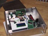
I recently finished my chassis for my project. size is 12" wide and 10" deep, with 1/2" sides, and 1/8" 6061 aluminum for the rest. I cut all the aluminum on my table saw with a 10" non-ferrous 72 teeth Freud blade, and had the machine shop at school cut the opening for the vfd.
--
Brian
I recently finished my chassis for my project. size is 12" wide and 10" deep, with 1/2" sides, and 1/8" 6061 aluminum for the rest. I cut all the aluminum on my table saw with a 10" non-ferrous 72 teeth Freud blade, and had the machine shop at school cut the opening for the vfd.
--
Brian
Attachments

The inside is quite ugly... my friend is working on the volume control circuitry now, using the burr brown pga2310, and I am just taking care of the control logic. I will eventually put connectors on the back, and make the insides prettier.
There are no screws visible on the sides or top. I used tapped blind screw holes in the sides, and the top is held on by the front and back, and easily removed by loosing the back with thumbscrews.
--
Brian
There are no screws visible on the sides or top. I used tapped blind screw holes in the sides, and the top is held on by the front and back, and easily removed by loosing the back with thumbscrews.
--
Brian
Attachments
Member
Joined 2002


Brian, that’s one fine looking chassis! Are there dados cut to hold the top plate in place? I was wondering if it might tend to resonate or buzz if its snug fit or held in place by gravity.
Do you plan on applying Dynamat to the back of the Proto-board?
Non-sequetor: Jason, who makes that speaker cable you showed us in the other thread?
-Dave
Do you plan on applying Dynamat to the back of the Proto-board?
Non-sequetor: Jason, who makes that speaker cable you showed us in the other thread?
-Dave
Member
Joined 2002
My grey stuff. you can email me and ill give you the email address of the person that gets it for me.
- Status
- Not open for further replies.