Hello BPBP users
I finally bought the following parts: BPBP, Hans Polaks VolCB pcb and the Maya controller. The only thing I'm missing is the nice 4 input extension board that Mr. Polak designed. I searched in the different threads about BPBP but could not find any information how to get it. Do you guys know how I can get this nice extension?
Kind Regards and Thanks in advance for any help
Phil
PS: I posted this also in "Bruno Putzeys Balanced Preamp - Group Buy Part 3" thread but it was intended for this thread. I hope it is OK to put the same post in another thread.
I looked for the extension board too but couldn't find any.
Seems like a group buy item only which has passed already and no one is offering on its own...
Seems like a group buy item only which has passed already and no one is offering on its own...
I expected them ready to be shipped ...
Sometimes waiting takes soooo long 😱
I wish someday to become like Amazon, but till then ... 😉
Regards,
Tibi
...The only thing I'm missing is the nice 4 input extension board that Mr. Polak designed. I searched in the different threads about BPBP but could not find any information how to get it. Do you guys know how I can get this nice extension?
...
In previous GB I have offered that board too. Interest was very, very low.
Regards,
Tibi
New firmware
Hi all ,
please find attached for testing purpose the version 1.3 that have 2 enhancements:
- set real number of input chanel
- set real gain of BPBP
Enter Settings menu >> turn encoder >>press Select button till you see:
- Number of input select >> turn encoder >>> with IR command volume up/volume down select how number of input do you have >>> press Mute from IR remote to save in EEprom memory >the press Select button till exit settings menu or go and modify real gain for your unit
- Real gain adjust select >> turn encoder >>> with IR command volume up/volume down select the real gain you have there , please bear in mind that the number on LCD is the grand from which you must minus the starting point gain in dB (you will figure out = Here is like this you will have for example a max number of 100 - number use internally in firmware 0-63 in every 1 db step) >>> press Mute from IR remote to save in EEprom memory >the press Select button till exit settings menu
Please remember that the first setting are for IR remote after you flash a new firmware because all setting from settings menu rely on IR command.
Also this is only for OLED version of Maya BPBP.
For LCD will come soon .
Please test and feedback to me.
Attachments
Hi all ,
please find attached for testing purpose the version 1.3 that have 2 enhancements:
- set real number of input chanel
- set real gain of BPBP
Enter Settings menu >> turn encoder >>press Select button till you see:
- Number of input select >> turn encoder >>> with IR command volume up/volume down select how number of input do you have >>> press Mute from IR remote to save in EEprom memory >the press Select button till exit settings menu or go and modify real gain for your unit
- Real gain adjust select >> turn encoder >>> with IR command volume up/volume down select the real gain you have there , please bear in mind that the number on LCD is the grand from which you must minus the starting point gain in dB (you will figure out = Here is like this you will have for example a max number of 100 - number use internally in firmware 0-63 in every 1 db step) >>> press Mute from IR remote to save in EEprom memory >the press Select button till exit settings menu
Please remember that the first setting are for IR remote after you flash a new firmware because all setting from settings menu rely on IR command.
Also this is only for OLED version of Maya BPBP.
For LCD will come soon .
Please test and feedback to me.
Already found issue with LCD printing volume /gain :
Here the version with bug corrected , please test this on.
Attachments
Will this be the actual firmware version delivered with the "sales" version from March 31st ?
All units will be shipped with firmware 1.2 which is tested and proved to work ok.
Fur further enhancements you need to be prepared to upgrade yourself.
Regards,
Tibi
Yes ,All units will be shipped with firmware 1.2 which is tested and proved to work ok.
Fur further enhancements you need to be prepared to upgrade yourself.
Regards,
Tibi
after testing will provide with version 1.4 for Oled and LCD
that will be the stable firmware with the latest enhancements.
Also Free Bascom can be used to upload new firmware to your unit.
For more info : https://www.mcselec.com/index.php?option=com_content&task=view&id=14&Itemid=41
on Windows only .
You just load the hex in buffer in programming windows and the Erase and program button.
For free download see the MCSelec site
Attachments

All units will be shipped with firmware 1.2 which is tested and proved to work ok.
Fur further enhancements you need to be prepared to upgrade yourself.
Regards,
Tibi
I would like to have those "new" features of the announced new firmware because I only got the "2 inputs" version of the BPBP.
Is it possible to have the delivery of my order delayed until the new firmware version 1.3+ (or 1.4 ? whatever it is actually named then) is ready for delivery ?
I don't have a programer and buying one just for 1 unit and getting accquainted to its functionality seems to me at least somewhat "over sized"... 🙄
Hi
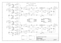
I am designing my own PCB to meet certain form factor requirements, it will combine Bruno's and Hans' designs and add an Arduino compatible MCU circuit. I "need" to add unbalanced RCA inputs and outputs for this to be compatible with my old design. What is your opinion on how to connect the unbalanced input? See attached schematic (or full schematic as PDF), I have drawn different options for RCA input in L and R channels.
I just cannot think this through properly, here is what I have been thinking so far:
First option connects RCA signal and ground as a differential pair to balanced input. I am slightly concerned as the input circuit is high impedance, also for the cable shield - although at source cable ground is connected to device ground. Also, the cable is not symmetric twisted pair, nor is the source impedance.
Second option connects RCA ground to the ground reference point. When this input is selected, it grounds the balanced-input cold wire. My concern here is the exposed ground loop current path, although it should not have big impact on this design.
Unbalanced outputs are just taken parallel to the balanced one, with their own series resistors.
Any thoughts?
Attachments
Last edited:
I don't have a programer and buying one just for 1 unit and getting accquainted to its functionality seems to me at least somewhat "over sized"... 🙄
My advice would be to pick up a USBtiny. The firmware keeps changing and you will most likely need it in the future.
I bought the kit from here
USBtinyISP AVR Atmel programmer for Arduino Bootloader | eBay
Will see if it comes and will work. For 10USD total this is acceptable risk.
Adafruit sells it for 22USD which is ok, but shipping to Estonia is 48USD which is not so ok.
USBtinyISP AVR Atmel programmer for Arduino Bootloader | eBay
Will see if it comes and will work. For 10USD total this is acceptable risk.
Adafruit sells it for 22USD which is ok, but shipping to Estonia is 48USD which is not so ok.
Look at the sch............ I "need" to add unbalanced RCA inputs and outputs for this to be compatible with my old design. What is your opinion on how to connect the unbalanced input? See attached schematic (or full schematic as PDF), I have drawn different options for RCA input in L and R channels...............
Pin1 and the XLR shell are connected to the enclosure. None of the pin1/Shell are connected to any part of the audio side.
The signal lines of the XLR are connected to Pins 2 & 3.
The RCA is connected to the same lines as pins 2 & 3.
Now consider the first input stage.
It reads the DIFFERENCE in voltage between pins 2 & 3. It processes that Difference and sends it's output via pins 2 & 3.
The amplifiying stages inside the Putzeys' vol pot don't care whether pins 2 & 3 are connected to the XLR or to the RCA. It reads the difference in the signal voltage.
Where the RCA do complicate the circuit, is that the RCA barrel becomes connected to Audio Ground when the relay activates. ALL the pins 3 are now connected to the Audio ground. That means the Balanced Impedance Inputs must not be used while the grounding of the RCA input is active.
There is an easy and cheap solution that overcomes this slight drawback.
Convert your unbalanced source to passive Balanced Impedance. i.e. make then a clone of what B.Putzeys has done for the Output of his balanced vol pot. He has used a passive Balanced Impedance Output. Just copy it at your unbalanced sources.
It is similar at the output.
When the RCA output is disconnected the Balanced outputs work properly.
If you connect the RCA unbalanced output, then the balanced outputs must NOT be used.
I'm not sure what solution you need at the output to allow both the balanced and unbalanced output to be active at the same time.
Maybe a Buffer on the two RCA lines would isolate it sufficiently to allow the Bal to work.
Last edited:
Look at the sch.
Pin1 and the XLR shell are connected to the enclosure. None of the pin1/Shell are connected to any part of the audio side.
The signal lines of the XLR are connected to Pins 2 & 3.
The RCA is connected to the same lines as pins 2 & 3.
Now consider the first input stage.
It reads the DIFFERENCE in voltage between pins 2 & 3. It processes that Difference and sends it's output via pins 2 & 3.
The amplifiying stages inside the Putzeys' vol pot don't care whether pins 2 & 3 are connected to the XLR or to the RCA. It reads the difference in the signal voltage.
I am just somehow confused by the fact that shield is part of the input signal on a high-impedance input. I think I am just thinking it too complicated.
Where the RCA do complicate the circuit, is that the RCA barrel becomes connected to Audio Ground when the relay activates. ALL the pins 3 are now connected to the Audio ground. That means the Balanced Impedance Inputs must not be used while the grounding of the RCA input is active.
I do not get this completely. The barrel is not directly connected to the audio ground in the option1? In the option2 it is, but does not connect pin 3s to it.
It is similar at the output.
When the RCA output is disconnected the Balanced outputs work properly.
If you connect the RCA unbalanced output, then the balanced outputs must NOT be used.
I'm not sure what solution you need at the output to allow both the balanced and unbalanced output to be active at the same time.
Maybe a Buffer on the two RCA lines would isolate it sufficiently to allow the Bal to work.
True, good point, thanks.
I mainly wanted to have these RCAs so that I can nicely use the custom-made rear panel of my older preamp design. But this causes unnecessary complications, after all I am putting balanced connectors to all my DIY devices and may not even need the RCAs. I think I will just remove all RCAs from this design and make a new rear panel. I can also get rid of some relays if I only leave 2 balanced inputs.
I don't understand your comment. The input to an RCA is a two wire connection. The signal Flows in through one wire and Returns via the other wire. Neither of these wires are a ground. They are both signal wires. Don't think of the second wire as a shield/screen.I am just somehow confused by the fact that shield is part of the input signal on a high-impedance input. I think I am just thinking it too complicated.
This makes the unbal quite different from the Bal input. With the Bal input we have two dedicated signal wires. The shield/screen is also dedicated to it's own job. It is there to attenuate interference.
What are your options 1 & 2?I do not get this completely. The barrel is not directly connected to the audio ground in the option1? In the option2 it is, but does not connect pin 3s to it.
B.Putzeys has two relay connected inputs.True, good point, thanks.
I mainly wanted to have these RCAs so that I can nicely use the custom-made rear panel of my older preamp design. But this causes unnecessary complications, after all I am putting balanced connectors to all my DIY devices and may not even need the RCAs. I think I will just remove all RCAs from this design and make a new rear panel. I can also get rid of some relays if I only leave 2 balanced inputs.
The unbal input is easily accommodated. It would be worth duplicating at least some of your multiple inputs as RCA. It increases convenience. It just means you cannot use a bal input at the same time as an unbal input. But that never happens if you have relays clicking in/out.
What are your options 1 & 2?
I draw two different ways of connecting unbalanced input, different for L and R channel.
The second one (R) is connected in a single-ended manner which I guess just wastes some of the capabilities of the input circuit.
To my opinion your first (upper) option is the best way to connect an RCA input. And your RCA output just seems fine to me. No reason why both outputs could not be used at the same time.Hi
I am designing my own PCB to meet certain form factor requirements, it will combine Bruno's and Hans' designs and add an Arduino compatible MCU circuit. I "need" to add unbalanced RCA inputs and outputs for this to be compatible with my old design. What is your opinion on how to connect the unbalanced input? See attached schematic (or full schematic as PDF), I have drawn different options for RCA input in L and R channels.
I just cannot think this through properly, here is what I have been thinking so far:
First option connects RCA signal and ground as a differential pair to balanced input. I am slightly concerned as the input circuit is high impedance, also for the cable shield - although at source cable ground is connected to device ground. Also, the cable is not symmetric twisted pair, nor is the source impedance.
Second option connects RCA ground to the ground reference point. When this input is selected, it grounds the balanced-input cold wire. My concern here is the exposed ground loop current path, although it should not have big impact on this design.
Unbalanced outputs are just taken parallel to the balanced one, with their own series resistors.
Any thoughts?
Since you have the option, you could connect all pin2 and pin7 of your input relays to chassis Gnd to prevent any crosstalk from unused inputs that are still receiving signals.
Hans
I bought the Maya controller with your VoICB stepped attenuator board from vicol-audio.
I admire the layout of that densly packed PCB but after a closere look have two "wishes" for a board version 2.0, if there ever will be one:
1) the placement of those direct "pot replacement connections" (6+2) is unfortunate, because the Hypex regulators are in the way making it necessary to have the PCB rising quite high above the BPBP board overlapping one of the Hypex regulators. If that connection would have been placed somewhat further left the VoICB would have fitted snuggly just above the small electrolyte capacitors and relays etc.
2) extending the PCB even further right would allow added mechanical support (and direct connection) to that input toggle switch connections underneath. Additionally another relay + resistors could be added then to increase the resolution of the stepped attanuator to may be 0.5 db (128 steps).
Just my thoughts (and suggestions) 😉
- Home
- Source & Line
- Analog Line Level
- Remote Control for the BPBP