High voltage electrolytics are sometimes reputed to be a bit more leaky if only used at low voltage. Leakage current reduces as the cap initially 'forms' and that happens best at higher voltages. Modern caps are much better than those of years ago though.
For reservoir caps it all makes zero difference. In your amp I think only the 47uF timing cap is going to be at all critical and here leakage is important... but it will be a constant that improves over time. It's not going to different one hour to the next.
I'll study everything else a bit later 🙂
For reservoir caps it all makes zero difference. In your amp I think only the 47uF timing cap is going to be at all critical and here leakage is important... but it will be a constant that improves over time. It's not going to different one hour to the next.
I'll study everything else a bit later 🙂
A film cap will always have much lower leakage than an electrolytic.
The CD4060 and 74 series chips are common logic types and while they are very sensitive to static that restriction only applies while they are not soldered in to a board (just loose on the table etc). As soon as they are in circuit the surrounding impedances reduce the static risk to zero. They also have built in protection (diodes) that are 'in circuit' once it is all connected up.
One condition can cause damage is working on equipment with a mains powered soldering iron that has significant electrical leakage, particularly if the amp was connected to a mains ground at the time.
http://www.circuitinsight.com/pdf/eos_exposure_components_soldering_process_ipc.pdf
I'm not so sure disconnecting boards and so on is going to prove much tbh because the circuit then powers up in a non valid state.
I would concentrate on getting a repeatable delay at the relay and if that is not happening then look simply at the inputs to the module and the related supplies and see what is different from one timing cycle to the next.
We're getting very deep into this considering this was all working OK until the recap... I keep saying this but don't loose sight of that fact.
Hei again and wanna say im sorry for the long delay. I think i burned myself out or something and my brain shut off regarding this and other matters. Maybe i took to much over my head with family, kids and lot of hifi-stuff.
Anyway i've been resting my head from all hifi activity now and feel better.
I wasn't sure either how to measure the delay cuz there is aint any to speak off. Any suggestions how to pursure this and get down to the bottom of this?
Anyway i've been resting my head from all hifi activity now and feel better.
I wasn't sure either how to measure the delay cuz there is aint any to speak off. Any suggestions how to pursure this and get down to the bottom of this?
I would probably go back to the beginning and look at the basic circuit you posted in post #1 and then look at all the variables to that section of circuitry. The simulation I did shows it works and gives a delay equal to the value of C755
Problem fixed. Finally puhhh...
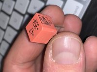
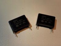
This 2 caps have failed and created lots of issues as we know.
One for the powerswitch and one for the relay.
Also found that the regulator 7805 somewhat leaked to the heatsink and to the input so threw in a
new one and isolated it from heatsink with siliconepad and plastic isolator around the screw.
They measured good in capacitance but when replaced with some Wima 0.01 X2 caps they amp started to work and delay is 2-3 seconds. More than enough.
Thanks to everyone involved!
Attachments
Last edited:
Hehe yes and i think my time off here and with hifi got me thinking outside the box.
Especially many thx to you Mooly
Especially many thx to you Mooly
- Home
- Amplifiers
- Solid State
- Relay timing

