I replaced the cap with another one (nichicon KA i think, blue sleeve) and no difference. Same time i went over everything once more and resoldered many places just to be sure, especially a earth connection that looked a bit bad and nothing new, it works exactly as before.
The formula for working out the delay is in the datasheet
With the values present, it should be 2.45 seconds
Brian
This isn't the chip though, this is the discrete module version which may be different.
If you look at the diagram of the module the voltage of Q16 base has to rise enough to allow sufficient current to flow into Q17 base (so voltage across R25 has to reach at least 0.7 volts before things happen).
In very approximate terms that means we need around 1.4 volts (across the cap before anything happens. In practice those transistors may start to conduct when Vbe reaches a lower value of say 0.45V or so, and that happens in under one second.
I would say if the amp is silent at power on then leave things as they are. Beware of increasing the cap value to much because when the circuit disengages the relay, the charge on that cap has to be dumped via the diode and a transistor to ground and a massive cap could cause high peak currents (although in practice I'm sure there wouldn't be a real issue).
I replaced the cap with another one (nichicon KA i think, blue sleeve) and no difference. Same time i went over everything once more and resoldered many places just to be sure, especially a earth connection that looked a bit bad and nothing new, it works exactly as before.
Exactly as before... as in?
Before the recap or still faulty?
I agree that it seems fast watching the video, but a short delay does fit the theory and simulation of a 180k and 47uF charging up... at least in that the simulation shows around 1 second before the final NPN transistor in that module conducts.
To make certain that it is all behaving correctly you could try adding another cap in parallel to the 47uF (say another 47uF) and see if the delay alters. A parallel 47uF (so approx 100uF total) would double the delay to 2 seconds (simulation result).
To make certain that it is all behaving correctly you could try adding another cap in parallel to the 47uF (say another 47uF) and see if the delay alters. A parallel 47uF (so approx 100uF total) would double the delay to 2 seconds (simulation result).
This isn't the chip though, this is the discrete module version which may be different
Ah yes, missed that, sorry
Brian
I agree that it seems fast watching the video, but a short delay does fit the theory and simulation of a 180k and 47uF charging up... at least in that the simulation shows around 1 second before the final NPN transistor in that module conducts.
To make certain that it is all behaving correctly you could try adding another cap in parallel to the 47uF (say another 47uF) and see if the delay alters. A parallel 47uF (so approx 100uF total) would double the delay to 2 seconds (simulation result).
I will try. Thx
Dis you measured the resistances present in the circuit? And voltages?
All resistors seems to be ok.. voltages i haven’t measured cuz i have no idea what they should be with this discrete module
Another notice; While checking around i noticed when i flip the main rock switch on the back to (”vacation”) that deactivates the standby function (amber led on front) it doesn’t turn off completely as it should, basically kill the power, the amber led just glowing little bit less bright and if i try to start it (normally you cant start it up if vacation is activated it tries to turn on but then turn off right away. So something is wrong for sure.
I spent now 6 h removing all boards, standby/ ato and more, doing severe checking with my dmm and everything looks good and nothing accidently shorted n so on, not what i can see..
What i myself dont get is how i still can have power if the switch is off position (vacation)? I tested the switch and other things but it works as it should.
If you don’t want to mess with electrolytics getting flaky you can use X7R ceramics for timing caps and never have to replace them again. You may need a bit higher value because of the voltage coefficient, if the difference between 3 seconds and 2.5 upsets you.
From what you say now it does sound like something has gone amiss during the recap. Look and see if the appropriate relays are dropping out as they should... in other words see why rails that should be killed by the switch are remaining active.
Don't loose sight of the fact that this is something untoward you have done so look more for the likes of solder blobs or incorrectly fitted parts rather than a part failure.
Don't loose sight of the fact that this is something untoward you have done so look more for the likes of solder blobs or incorrectly fitted parts rather than a part failure.
Thanks everybody.
I have been spending serious amount of time to find the fault (checked if i made mistake, soldering, bridges etc..) even with a 30x magnifier but haven’t find anything.
I’m playing now on it and everything seems fine and it sounds very good. I haven’t had time tontry out that 47uf x2 cap yet but will soon.
Amp draws about 52w idle, is that normal?
52W sounds a lot... it's a complex amp though.
Lets see, the bias current (70ma on 130 volt total supply) suggests approx 20 watts dissipation in the output stages alone, so yes, maybe its about right when everything else is added up.
Lets see, the bias current (70ma on 130 volt total supply) suggests approx 20 watts dissipation in the output stages alone, so yes, maybe its about right when everything else is added up.
Ok good to know.. the cooling fins doesn’t get that hot even though bias is 7.5mA (max in schematic) but the extra fins where the gainstage and the buffert is really hot��
My old Nad 216thx (also recapped) pulls 67w idle even though its not that complicated.
Anybody know how this ISC curcuit really works? In the manual says adjust to load 15w and 160w but whatever i get i get 1.445v (before recap too)
Heard the opamp could be the issue (cp082) but nothing happened when i changed. Also replaced the 1015/1815 around this and checked resistors but same. Could the thyristors be damaged? (Philips BT151-500R)
I've just quickly looked at the ISC and it seems to work by looking at amplifier output voltage at the speaker feed and also the current drawn and sensed across R716.
A low impedance load will draw more current for a given output voltage and so this current can be sensed and compared to a reference value (say for 8 ohms) and if the current is 'low' the ISC will turn on the thyristors and allow the high voltage full wave rectified but unsmoothed supply from the bridge (B702) to increase the rail voltage by allowing the thyristors to conduct and apply this voltage to the reservoir caps.
If the current increases relative to the output voltage (low impedance) then the thyristors are off and the amp operates on the lower rail voltage.
That's how it seems to work from a quick look at the circuit 🙂
OK thx for that thorough of how it works. Very helpful.
So if the voltage is +/-64v how much is the low and high voltage? The caps are rated 80v. Been some issues in this amp i’ve read that it’s blowing caps on the rails.
Is +/- 64v maximum?
So if the voltage is +/-64v how much is the low and high voltage? The caps are rated 80v. Been some issues in this amp i’ve read that it’s blowing caps on the rails.
Is +/- 64v maximum?
I have 2x of those thyristors (new ones but brand is nxp) thinking of replacing them. I don’t know how to test them.. with my Brymen dmm they show 0.021v in diode mode) either way (in curcuit i must add) But not sure how these work. I’m learning or try to.
Also thinking again going over this powerboard to check for mistakes regarding previous ”problem”.
Also thinking again going over this powerboard to check for mistakes regarding previous ”problem”.
One thing i found odd was that those 2 res. And 2 caps in the schematic is 100K v 10uf... colourcode confirms it and caps had it printed too. Wonder why Nad have adjusted that and not mentioned it. Somebody screwed upp in China factory hehe?
Attachments
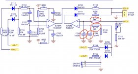
The circuit shows bridge B701 being fed with 33 volts AC which would give a rail of 46 volts DC approx. That is the 'low' rail voltage and would be the one you would see when current demands are very high such as working into low impedance loads. The 64 volt rail is the high one and you get that when the thyristors are conducting.
Tbh, given that we listen mostly at levels around 1 watt or less you would probably never see this part of the circuit come into operation in normal home use. How many amps do you know of that would call a -/+46 volt rail "low". You would be able to deliver a sustained 100 watts rms into 8 ohms from that supply voltage.
The thyristors won't be faulty, they are super rugged. The failure mode would be a short from anode to cathode (you have to check them out of circuit) but they wouldn't give you this fault anyway. They would just give a stuck high voltage rail.
They operate a bit like a transistor but can only ever be on or off, nothing in between. Once triggered on they remain on until the current reduces to below the 'holding' value which will be a a few milliamps at most. That happens automatically here because the input side is half wave rectified pulses and so the voltage they see on the input falls to zero every half cycle.
The diode cap and resistor combination (1meg/10uf) form a filter and sample/hold function with a short hold time. Values might be tweaked in production to prevent the ISC operating or dropping out when it really shouldn't. The 100k is always trying to discharge the caps (via the 1 meg). Maybe the circuit was cycling to much, perhaps with certain kinds of music.
- Home
- Amplifiers
- Solid State
- Relay timing