I’ve now tried adding 47uf extra capacitance to my ”start-up” curcuit and (total now about 95uf) and first power on while been of power for a day was a quite long, maybe 5 seconds.
Second start-up about 10min after shutdown took about 1 second or perhaps if i guess twice as long as before but still too short.
Checked voltage after about 10min and cap is empty (0.001v)
Also replaced all resistors (yes ALL) and still function same but have to say all metalfilm sounds quite different from carbonfilm.
Still haven’t found anything out of ordinary... thought inwas gonna catch a solderbridge or whatever while doing this bit no, nothing.
EDIT: checked starting up again after 10-11min and same about a sec or less
Last edited:
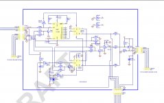
Lets go back to basics and begin by monitoring the voltage on pin 6 of the IC module. That drives the speaker relays via transistor Q715.
When pin 6 falls low enough so that the Zener D718 can conduct is when the relays will pull in.
So things to check.
1/ That the supply voltage marked +V34 remains fairly constant when the relay is on or off.
2/ That the pin switches cleanly between near zero volts (when the relay will be ON) and the supply voltage we measured above (when it will be OFF).
3/ Monitor the 'Protect T' line that goes to pin 8 of the module. What voltage do you see when the unit gives the expected longer switch on delay?
Is the voltage different when it does the short delay?
Ok, question right away, on nr1, you mean that if the unit is in standby this should still read +34V?
BY the way, pin 6 have never been connected. I thought it was my mistake but looked but on many photos i took when i got the amp and it confirms it. Pin 6 is not in use.
The 34 volt supply is fed from the main (large) transformer and not the standby one and so all the time relay R701 is engaged (the standby relay) you should be seeing the 34 volts.
Reservoir cap C765 is deliberately small in value (22uF) and this fact means it is highly stressed and so should be a good quality part with high ripple rating. It is small in size to ensure the 34 volt line as a small time constant i.e. it falls away quickly on power off.
Reservoir cap C765 is deliberately small in value (22uF) and this fact means it is highly stressed and so should be a good quality part with high ripple rating. It is small in size to ensure the 34 volt line as a small time constant i.e. it falls away quickly on power off.
BY the way, pin 6 have never been connected. I thought it was my mistake but looked but on many photos i took when i got the amp and it confirms it. Pin 6 is not in use.
That sounds a bit odd because pin 6 is clearly shown in the discrete module circuit as being the 'output' pin. It connects to transistor Q17 in the module which when it turns on pulls the line low and turns on the relay drive transistor... just like the chip.
Running out of ideas for you to try in this case 🙂
As I mentioned way back, don't lose sight of the fact that this problem started after you recapped it and so we are likely still looking for a man made error somewhere.
The 34 volt supply is fed from the main (large) transformer and not the standby one and so all the time relay R701 is engaged (the standby relay) you should be seeing the 34 volts.
Reservoir cap C765 is deliberately small in value (22uF) and this fact means it is highly stressed and so should be a good quality part with high ripple rating. It is small in size to ensure the 34 volt line as a small time constant i.e. it falls away quickly on power off.
Yes, ok so that was my thinking too. Thought i was really dumb there for a moment. Haha
Anyway, yes the C765 is a Panasonic FM cap rated at 22uf/50v. And should be a good part. The orginal was really bad, measured about 2uf if i remember correct.
Before/ after pic
Attachments
That's interesting if you actually measured the part and it really was down to 2uF because as I mention, that part is highly stressed.
It is stressed simply because the current draw of those rails will cause a large ripple component (voltage) to appear across the cap and so that leads on to the fact that a correspondingly high ripple current flows in the cap... high in relation to its small size... and that causes local heating and deterioration over time.
Why not fit a 2.2uF in its place and see if the unit behaves as it once did. You say the 'fault' occurred after the recap and now go on to say that a vital part that was replaced was effectively non-functional as proved by measurement.
So put it back to that state and retest 🙂
That's interesting if you actually measured the part and it really was down to 2uF because as I mention, that part is highly stressed.
It is stressed simply because the current draw of those rails will cause a large ripple component (voltage) to appear across the cap and so that leads on to the fact that a correspondingly high ripple current flows in the cap... high in relation to its small size... and that causes local heating and deterioration over time.
Why not fit a 2.2uF in its place and see if the unit behaves as it once did. You say the 'fault' occurred after the recap and now go on to say that a vital part that was replaced was effectively non-functional as proved by measurement.
So put it back to that state and retest 🙂
Hehe, well but thing is i’ve tried the amp after that cap (first cap i replaced cuz i saw it was so bad, see pic) and few weeks later the other ones so pretty sure its not that one. But i was thinking what happens to the curcuit if its so low value? Lots of ripple reaching the protection ic? Have it been somewhat damaged cuz of the cap? The amp doesnt have any other filter before this either except a fusible reisistor..
I will try tgis werkend to measure those voltages on the pins to see what i get
Last edited:
One thing i noticed now (and my wife) while powering it up left (mostly) channel makes a ”böööppp” sounds almost digital, sound for a second before /or when relays turn on..
This have come after adding the extra 47uf cap so i think i’ll remove it..
This have come after adding the extra 47uf cap so i think i’ll remove it..
I can't see the module being damaged. There is a series 10k (R768) in the supply and a 4.7v Zener shunt in the module (used as a shunt stabiliser) so nothing bad will happen. The 10k limits current to non destructive values.
The Zener means you should see a constant 4.7 volts on pin 8.
The Zener means you should see a constant 4.7 volts on pin 8.
Ok i measured now... not sure how i can measure when relays are open?!
This is the values i get when unit is on and ready:
+34v is 38.25v exactly where schematic shows between the 220R and the 5.6k res.
-After the 220R i have 32.75v
Here is the pins:
1. 0.002v
2. -0.004v
3. 0v
4. 0.001v
5. -33.77v
6. 0.021v
7. 1.432v
8. 4.38v
All this values are contstant, 0.1v maybe up or down, nothing major
I would say if the amp is silent at power on then leave things as they are. Beware of increasing the cap value to much because when the circuit disengages the relay, the charge on that cap has to be dumped via the diode and a transistor to ground and a massive cap could cause high peak currents (although in practice I'm sure there wouldn't be a real issue).
Well, now i have an issue worse than before. After removing the 47uf, i now have totally 47uf as schematic says. I still have noise when turning it on. Like i said before; ”scratchy/ digital thumpp” everytime i turn it on. When turning off i don’t hear (yet) anything special...
diode or transistor blown i guess or something else.
I'm still here 🙂
We are getting nowhere fast with this and so I think a re-evauation is needed and to begin from basics. I'll have a think how to proceed...
We are getting nowhere fast with this and so I think a re-evauation is needed and to begin from basics. I'll have a think how to proceed...
Thx for being here.,.🙂
I think somehow i got the noise away now, i replaced Q715, D713/718 and D719. I tested few times a cant hear anything now. I only tested with a small small 3” and last time i heard it it was on my high sen speakers...
Did you check pin voltage, make sense to you? +34 quite high right?
I can’t myself make anything out of it.
Can it be something with this ”Ato” Board? Seem to control everything and the switch on the front as well. Switch comes in on the 6-pin (bottom) and pin 4. And yes it’s also recapped.
Attachments
Last edited:
BY the way, pin 6 have never been connected. I thought it was my mistake but looked but on many photos i took when i got the amp and it confirms it. Pin 6 is not in use.
This is a crucial bit of information... and I just can't figure this out... it doesn't seem right.
If we look at the circuit we see that relay driver Q715 is normally OFF. That means no voltage on the relay coil and so no speakers connected.
To turn on Q715 we pull the base toward ground which means that Zener diode D718 anode (bottom end of it) has to be grounded.
If pin 6 is not connected then I can't see any way the transistor can be turned on. The line marked PT-Out is presumably 'protect out' and does indeed go to Q718 which appears to be used to switch other functions such as muting.
So that is a real puzzle. PIN 6 not connected doesn't sound correct. Are you sure you are reading the pins from the correct end. Look at part references, don't rely just on one board marking.
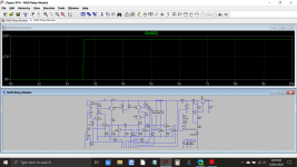
If pin 6 were connected then the circuit would behave as intended. I've even run a simulation of the module and it seems to give a 2.5 second delay but there is a problem... the logic levels are 'wrong' to drive the relay driver transistor and I can see why. It is because of R23 in the module pulling the driver transistor base to ground via Q19 and R26.
That's as far as I have got 🙂
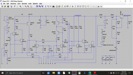
Here is the sim showing the relay closing after 2.5 seconds (with R23 not in circuit). The second image shows the relay voltage coming up to around 33 volts.
Third image is with R23 connected. It is keeping the driver transistor in conduction all the time. The module still switched correctly, its just the transistor is being held on.
I'll look at the resistor chain and Zener tomorrow. The Zener is a common tactic used to translate between logic levels.
Edit... I've attached the .asc file if anyone want to have a play.
Attachments

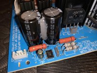
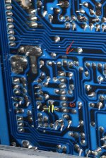
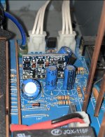
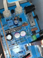
This pics are taken first time i ever opened this amp.
As you can see there is a pad for a smd res or cap but shows that it just got flown in factory so nothing seem to have fallen off.
2 pics from above with the module and the surrounding components including some of the +/-18v supply
As you can see there is a pad for a smd res or cap but shows that it just got flown in factory so nothing seem to have fallen off.
2 pics from above with the module and the surrounding components including some of the +/-18v supply
Attachments
Last edited:
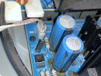
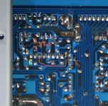
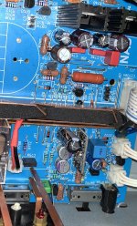
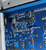
This is how it looks now (except that extra 47uf cap on pin7 underneath)
Very hard to take a good photo on shiny tin i noticed 🙂
Very hard to take a good photo on shiny tin i noticed 🙂
Attachments
-
 C4763FC3-5949-4904-A8F2-2709C5C94672.jpg596.1 KB · Views: 77
 -
 3C9C6ABD-DBC8-462E-A0AD-CC723E26D7FB.jpg1,015.2 KB · Views: 111
 -
 23BBD246-3BBA-4D2A-9BE5-8846F17FA7E6.jpeg871.9 KB · Views: 77
 -
 891850D4-9EDF-4648-AE21-2B75F468C552.jpeg957.2 KB · Views: 87
 -
 CB73ADED-FEB2-46BB-9583-58A14B571731.jpeg775.9 KB · Views: 75
 -
 87A24789-6170-4B40-8F99-254AED826CF4.jpeg883.3 KB · Views: 76
Thanks Mooly for your time consuming calculation
I was thinking i show you myself. Maybe my 41 yr old eyes is bad 🙂
I was thinking i show you myself. Maybe my 41 yr old eyes is bad 🙂
Hmmm. Nope, that definitely looks not connected to me as well... and that just can not be with the circuit as drawn.
As mentioned, the bottom end of the Zener must be able to pull the base of transistor Q715 to zero volts for the transistor to turn on.
Is there another path?
Not that I can see. The PT-Out line goes via a 100k to Q718 base. In other words Q718 also expects that line to switch. And that has to be via the modules 'Open Collector' output on pin 6.
On the right hand pad that is open circuit I can see a small arc (a scratch) on the board as if a soldering iron has swept over there. Is it possible you have inadvertently caught that pad with a hot iron and removed the solder?
Does the right hand end of that pad go to the Zener as expected?
(I figured the logic levels out... I had missed out R767 which is a pill up resistor. So it does all work correctly)
- Home
- Amplifiers
- Solid State
- Relay timing