Eleveniseven,
Amplifiers do not normally 'filter' 2nd harmonics, and they do not normally 'filter' 3rd harmonics.
Musical instruments Produce harmonics, 2nd, 3rd, etc.
They do not normally produce a perfect sine-wave without any harmonics.
Those harmonics are a natural part of the characteristic sound of those instruments.
If we want to retain the sound of those instruments, we do not 'filter' the original natural harmonics that the instruments produce.
Harmonic distortion means that harmonics are added that were not in the original music instruments natural sound.
Natural harmonics are one thing.
They are not the same as harmonic distortion created by an amplifier, and are not the same as harmonic distortion created by a loudspeaker.
The key is to understand the musical instrument harmonics, versus the amplifiers harmonic distortion.
The amplifier and the loudspeaker add some level of additional harmonics to the musical instrument's sound. Those added harmonics are called harmonic distortion (emphasis on the word distortion).
We try to make amplifiers that do not Produce their own 2nd harmonic distortion, and their own 3rd Harmonic distortion (or higher orders of harmonic distortion either).
No amplifier is perfect, although often the levels of harmonic distortion are extremely low.
And some prefer a small amount of [added] 2nd harmonic distortion.
As a general rule, many single ended amplifiers produce some 2nd harmonic distortion.
Many single ended amplifiers have dominant 2nd harmonic distortion.
And, as a general rule, many push pull amplifiers produce less 2nd harmonic distortion,
they tend to cancel the 2nd harmonic distortion of their own output stage.
But they do not cancel the 2nd harmonic of the musicial instrument's sound.
Many push pull amplifiers have dominant 3rd harmonic distortion.
All generalizations have exceptions.
I think you may be confusing the 'cancellation' of the push pull output stage's 2nd harmonic distortion; versus the 'filtering' of a musical instruments natural 2nd harmonic.
Good amplifiers do not 'filter' the musical instrument's 2nd harmonic, a wideband audio amplifier includes the musical instrument's fundamental, and all of its natural harmonics.
I hope that does not cause further confusion.
Last edited:
Thank you. I indeed was confused about that very matter.
Having learned that…. Where does ultra linear fit into the harmonic distortion order then?
Either push pull or ultra linear couples the output tubes in parallel or series respectively..
Or am I lost on that too? I’m obviously not an EE here. But I am attempting to learn. Lol
Old dog, new tricks and such
I’m asking because I bought a couple Zkit boards as well. I heard them once years ago and was in love immediately. I’m looking forward to being able to compare and contrast these amps
Last edited:
Thank you. I indeed was confused about that very matter.
Having learned that…. Where does ultra linear fit into the harmonic distortion order then?
UL fits in by acting as a "correction" of distortion faults. Both SE and PP can use Ultra Linear (or screen taps).
I've found that amps like this A12 can sound good with certain types of music, if you limit the music played in frequency response reproduction needed and to selections that don't highlight the high distortion. Solo Sax smooth jazz with no vocals and no real bass, like Kenny G for example. Play something like Pink Floyd: Time on one of these, and all the flaws become glaringly apparent.
It's why sometimes you hear people say "an SE amp isn't good for playing rock music". "A high distortion, limited frequency response amp isn't good for playing difficult to reproduce music" is what they are really saying. A good SE amp sounds good playing any kind of music you want to listen to.
Thank you
I didn’t mean to derail the thread. I just found this after I ordered my A12 and I really want to tinker with it and get the most from it I can while I wait on my Zkits.
I listen to a wide range of stuff from nightingale Cummings, Tom waits, Floyd, to Mazzy star, tori Amos, Adem, Bon Iver.
I really want to bring out every detail I can find in these
My reisong arrived. I have to say I like it!
It’s just half *** set up through some old dynaco A25, using a schiit audio modi multi it dac.
As is this is not bad!!
It’s just half *** set up through some old dynaco A25, using a schiit audio modi multi it dac.
As is this is not bad!!
I did finally got this amp to behave with the iron it came with.
I was able to reduce the distortion 10 fold, get an honest 5W of power and measurably extend the frequency response. Listening to it, the bass exists, where is was just totally missing before and it's very pleasant to listen to now without needing a powered sub and $3000+ 100db speakers.
Out of the box I wouldn't recommend this as a purchase, but with these mods applied, it's now a good sounding amp, especially at this price point.
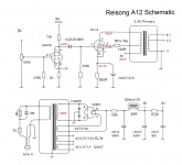
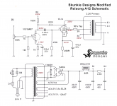
Here are the before and after schematics, and links to the video testing and two others covering the DIY mod process. A handful of passives and a different rectifier tube, that work together to change some key operating dynamics, transform this amplifier!
Boyuurange Reisong A12: Initial Modification Results = Win! - YouTube
Boyuurange Reisong A12: Doing the Mods Video #1 - YouTube
Boyuurange Reisong A12: Doing the Mods Video #2 - YouTube
I was able to reduce the distortion 10 fold, get an honest 5W of power and measurably extend the frequency response. Listening to it, the bass exists, where is was just totally missing before and it's very pleasant to listen to now without needing a powered sub and $3000+ 100db speakers.
Out of the box I wouldn't recommend this as a purchase, but with these mods applied, it's now a good sounding amp, especially at this price point.
Here are the before and after schematics, and links to the video testing and two others covering the DIY mod process. A handful of passives and a different rectifier tube, that work together to change some key operating dynamics, transform this amplifier!
Boyuurange Reisong A12: Initial Modification Results = Win! - YouTube
Boyuurange Reisong A12: Doing the Mods Video #1 - YouTube
Boyuurange Reisong A12: Doing the Mods Video #2 - YouTube
Attachments
Thank you very much Stephe!
i feel like my ears must be crap, lol, mine has very present bass, and even brand new out of the box is pretty pleasing.
I cant wait to see how things go with these mods!
i feel like my ears must be crap, lol, mine has very present bass, and even brand new out of the box is pretty pleasing.
I cant wait to see how things go with these mods!
stephe,
If you test the harmonic distortion at 40Hz, and compare it to the harmonic distortion at 1kHz, it will become quite easy to conclude whether the '50% UL tap' output transformer is push pull, or is single ended with an air gap.
At 1 or 2 watts and 40Hz, a small push pull transformer will look awfully saturated and non-sinusoidal, but not so bad at 1kHz.
I took a Dyna A470 push pull output transformer, and removed all of the interleaved E's and I's (laminations).
Then I lined up all the E's on one end, put a layer of Kapton tape over the open ends of the E's, and then put all the I's on the top of the Kapton tape (The tape is the spacer of the 'Air Gap').
That makes the push pull transformer into a single ended transformer.
The complete end to end primary winding was used, B+ to Plate.
There is less primary inductance than with interleaved E's and I's; but with the 'air gap', the laminations are not saturated from the 50mA DC quiescent plate current.
With negative feedback from the 16 Ohm tap to the cathode of the Triode-wired EL34, the overall amplifier low frequency response was -3dB at 15Hz and 60kHz, relative to 1kHz.
Later, I used the same 'air gapped' A470 with a KT66.
I connected B+ to one primary plate lead, the output tube plate to the other primary plate lead, and a 100 Ohm resistor from the primary center tap (50%) to the output tube screen.
That made it a 50% "Ultra Linear" circuit.
This is very interesting!
The OEM output transformers on my similar A9 produced awful looking sine waves but had attributed this to their smallness and quality issues. I have no idea what the UL tap percentage was and have long ago replaced them with Hammond iron.
Are you sure, that tiny OPT working well with -over- 70mA standby current at 20Hz?
Highly doubt they are great, and of course there is no way of knowing what any of the parts are rated at, but is sounds massively better.
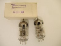
Sorry for the late reply. I was just wondering if these, "1960’s NOS pair of GE 6V6G ST style audio/guitar amp tubes", for sale locally would work in the A12?OK this is a total win for zero effort. I ordered a pair of cheap JJ 6V6S tubes, replaced the EL34 tubes running at 52% dissipation with these 6V6s tubes that are running at 90-92% dissipation, and then moved the 8 ohm load to the 4 ohm tap to get the reflected impedance close to what a 6V6 wants (I know this is less than ideal...), the usable power doubled and the distortion is less than 20% of what it was. I did try running the EL34 off the 4 ohm tap and saw a very minor, about 1/2% reduction in THD.
We now have 1W at 1% (instead of 6%), 2W at 1.5% (instead of almost 9%) and 4W at 4% (God only knows what % with the other tubes at 4W). Again, not changing anything else other than these 2 output tubes. It still has weak bass (OT issues?) and I believe can be further improved but this confirms the tube bias for the delivered EL34 is so far off, anything else done without addressing that, such as changing to a KT66-77 or different rectifier tubes/other tube rolling, isn't fixing the problem to any measurable degree. Changing these 2 tubes turned this from a really bad sounding amp IMHO to something decent and maybe with a coupling cap change and a few other minor tweaks will be even better. This does confirm my belief that an SE amp wants to have the output tubes run hard to sound good!
I still want to try some internal mods to use 7591a tubes biased correctly, which should work fine with the 3.2K OT using the correct taps, possibly try setting up the EL34 tubes correctly and then tinker around with the driver tube setup/coupling caps etc., but for anyone not interested in going inside the amp, some 6V6 tubes are the ticket! Below are the two THD vs power curves.
Seller said, "I ran these for an hour each when 1st purchased to make sure there were no issues with either and they both sounded great and produced a nice and warm vintage tone."
I apologize if links aren't allowed.
https://www.kijiji.ca/v-amp-pedal/new-glasgow-ns/ge-6v6g-st-style-nos-guitar-tubes/1612251238
The seller will be in my town this Saturday, so this is a time sensitive, if anyone knows the answer I'd really appreciate it!!Sorry for the late reply. I was just wondering if these, "1960’s NOS pair of GE 6V6G ST style audio/guitar amp tubes", for sale locally would work in the A12?
Seller said, "I ran these for an hour each when 1st purchased to make sure there were no issues with either and they both sounded great and produced a nice and warm vintage tone."
I apologize if links aren't allowed.
https://www.kijiji.ca/v-amp-pedal/new-glasgow-ns/ge-6v6g-st-style-nos-guitar-tubes/1612251238
Hi Stephe, I have a A10 with the stock 6N2 pre drivers and the stock JJ-EL34 outputs. I got the amp about about 2 years ago and it sounded totaly flat. I tried it out a few months ago and found it was not too bad for the first 10 minuets but got more flat the longer it was on. I was going to use if for "decoration" it was that bad, until I saw your youtube video on the mods. I did not have all the parts in hand but I found a 1K resister and a 100uf cap and added them to the EL34. Bang! The amp was like a totally new amp. For anyone who has the A10 you can in 5 minuets make it into a great sounding amp. I now have all the parts here to do the full mod.Highly doubt they are great, and of course there is no way of knowing what any of the parts are rated at, but is sounds massively better.
My real question is regarding the input tube and PS. For now I am planning to stay with the 6N2 pre drivers. I got in the Rocket 6N2P-EV and was hopeful they would work well. After install them they worked but my 60Hz hum which was quite low is now around 3 times louder.
The bass from the Rockets is way better which is needed ,because my bass is crap right now, but the hum makes them unusable. I don't know if its a mismatch or just the PS.
I have the new 5AR4 rectifier tube on the way and plan on going through the whole PS circuit. I was going to be cheep and leave the stock tube in and that's why I did not increase the EL-34 current much. I see the other guy posted the schematic of the A10 and it uses a 330uf+22uf+150uf. Ours came with the 22-150-22uf. I'm going to guess that the 330uf will be OK with the 5AR4.
The real question is my choice of filter caps I plan on adding. Its a 440v run cap 40uf. I think I can fit it in the box. Has anyone used a run cap for a PS filter cap? I'm thinking the impedance is lower than a electrolytic but I can't fine a specification.
I do have a few scopes and can set up a test bench in the future but for now I was just going to do a few changes and see how it goes.
Thanks everyone.
Dave
Attachments
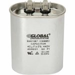
The first cap after the rectifier needs to be under a max of 60uf, I like to keep it 40uf max. And a run cap works fine for PS filtering, just make sure it is a run cap and not a start cap!Hi Stephe... I see the other guy posted the schematic of the A10 and it uses a 330uf+22uf+150uf. Ours came with the 22-150-22uf. I'm going to guess that the 330uf will be OK with the 5AR4.
The real question is my choice of filter caps I plan on adding. Its a 440v run cap 40uf. I think I can fit it in the box. Has anyone used a run cap for a PS filter cap? I'm thinking the impedance is lower than a electrolytic but I can't fine a specification.
I do have a few scopes and can set up a test bench in the future but for now I was just going to do a few changes and see how it goes.
Thanks everyone.
Dave
Try DC Link caps instead - they sound great and are smaller and rectangular. I use a Kemet one always as the last
PSU cap, e.g. 10uF. Very smooth and nicely detailed.
This is a bigger mod but one I've done to my amps - using a 2P29L (in triode) DHT in the input in filament bias, gain of around 10. Should be just enough with an EL34 in triode. I use a Rod Coleman filament reg on each one. No need for a heat sink if it's mounted on the chassis - filament current is 120mA. There's a big thread on using the 2P29L and how to use filament bias. A DHT makes a big difference in the input. You might need to take the filament supply outboard. If you want to improve it still further use a couple of Hammond chokes in it. I only mention this because it made a massive difference in my amps using a DHT driver.
It's a loctal socket. Looks like the hole in the top plate is wide enough at least.
Last edited:
Hello Stephe,
first of all: Thank you very, very much for your work on this amp! I bought it for playing around (with some fullrange horn speakers) and have most, but not all, parts lying around. I am very interested in your mods.
Coming from transistor devices, I principally understand what is going on in the circuit and your changes. I would like to start with the changes in den EL 34 stage and the rectifier section.
What I wonder is: Can the 5Z4P stay with these mods until a 5AR4 arrives. From the data sheets, I know that with a changed cathode resistor under full load on both channels, the current will be more than 125 mA.
Did you try this and would it be ok to do the mods step by step?
Any advice would make me happy (and please excuse my english as I am from germany).
- Home
- Amplifiers
- Tubes / Valves
- Reisong A12 review