Chris Hornbeck,
You said:
"Early single DAC Cd players don't really have a phase shift difference between channels, but rather a time shift. It's about 1/4 inch at speed of sound, so not terrible."
I really wish I had an old single DAC CD player . . .
Then I would take my Denon Audio Technical CD, and select the 19,999 Hz L+R (dual) sine waves.
Then I would set my 2 channel Tektronix digital scope for 'Measure Phase'.
(First I would compensate my probes on the scope channels they would be used on).
Then connect both probes to the 19,9999Hz from the CD player Left Channel out, and check that the phase readout is 0 degrees (Phase of scope CH1 / probe 1; versus CH2 / probe 2). That verifies the scope / probe calibration.
Then connect the probes, CH1 to Left, and CH2 to Right of the CD player.
I am pretty sure that the scope phase readout would be about 81.6 Degrees relative phase difference.
Call that phase, or call it time difference . . .
The sine waves would not come out at the same phase or time (just like some L & R amplifier channels that do not have exactly the same phase or time out).
For an amplifier, just send a square wave to both L and R inputs, and measure the phase / time difference at the output.
I admit this is one of the 'inner layers of the Onion', but I believe it does exist.
But finding very old CD players at Goodwill is becoming extremely difficult; and the chance that one of them is a single DAC model narrows the field even more.
One early CD player used 14 bit DACs, instead of 16 bit DACs.
Who even remembers that?
Last edited:
Waiting on some tubes and a few parts before the real fun begins 🙂
Did you fancy the 7591 in the end? Or waiting on different driver tubes?
There is a difference between phase and time, as there is between phase and polarity, and both of these are commonly confused. But it's outside the scope of this thread.
All good fortune,
Chris
All good fortune,
Chris
Did you fancy the 7591 in the end? Or waiting on different driver tubes?
I'm still waiting on some 7591 to try. I'm putting this whole thing on hold a few days waiting on parts etc. I haven't really decided on any path yet, lots of good options!
Chris Hornbeck,
Agreed. Yes, it is more complex than most readers will bear to read, in a simple thread.
But, simply . . .
Two equal frequency and equal amplitude sine waves that have a time difference versus each other, will also have a phase difference.
That, for an example is the basis of 2 Phase Power, and also for 3 Phase Power.
A small, constant time difference between 2 equal frequencies will cause less phase difference if the frequency is low (say 20Hz), and will cause more phase difference if the 2 frequencies are 20kHz (until the case where the time difference is more than 1/F, and we are going beyond 360 degrees; when it will now go in phase and out of phase, and in phase again, modulo 360 degrees).
And even more commonly mis-understood, the concept of Group Delay.
1. A Tektronix Digital Video Analyzer was able to discover an engineering defect in a Digital Video Product.
The Digital Video signal is sectioned into Frames; but there is a first half to the frame, and a second half to the frame.
The defective manufacturer's product took the second half of the first frame, and "married" it to the first half of the second frame.
That is a violation of the Digital Video Standard.
Now, what difference did it make?
Nothing, if you use the human eye, it can Not see the difference (nobody ever saw the difference).
2. What I am trying to illustrate about time, phase, etc. is that sometimes it matters, and sometimes it does not matter.
But some thread readers worry about the smallest "problem/defect".
When it comes to 'problems' some are the outer layer of the onion, I remind readers to throw that layer out, do not eat it.
Back when the single DAC CD players were being produced, some Hi Fi enthusiasts were saying they did not want to ever have to listen to such a player.
Just tell them to turn the left ear 1/8 inch forward, and the right ear 1/8 inch rearward, and the 1 DAC CD player problem is solved.
Or is the time difference the other way, I would have to turn the left ear 1/8 inch rearward, and the right ear 1/8 inch forward.
That only works for loudspeakers in a room.
It does not work for headphones . . . Are any of you headphone listeners worried that you might have to listen to a single DAC CD player?
3. I apologize, I often write threads just to cause some of the readers to stop worrying about trivial matters in their Hi Fi,
when there are so many other more important glaring problems.
Last edited:
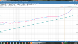
OK this is a total win for zero effort. I ordered a pair of cheap JJ 6V6S tubes, replaced the EL34 tubes running at 52% dissipation with these 6V6s tubes that are running at 90-92% dissipation, and then moved the 8 ohm load to the 4 ohm tap to get the reflected impedance close to what a 6V6 wants (I know this is less than ideal...), the usable power doubled and the distortion is less than 20% of what it was. I did try running the EL34 off the 4 ohm tap and saw a very minor, about 1/2% reduction in THD.
We now have 1W at 1% (instead of 6%), 2W at 1.5% (instead of almost 9%) and 4W at 4% (God only knows what % with the other tubes at 4W). Again, not changing anything else other than these 2 output tubes. It still has weak bass (OT issues?) and I believe can be further improved but this confirms the tube bias for the delivered EL34 is so far off, anything else done without addressing that, such as changing to a KT66-77 or different rectifier tubes/other tube rolling, isn't fixing the problem to any measurable degree. Changing these 2 tubes turned this from a really bad sounding amp IMHO to something decent and maybe with a coupling cap change and a few other minor tweaks will be even better. This does confirm my belief that an SE amp wants to have the output tubes run hard to sound good!
I still want to try some internal mods to use 7591a tubes biased correctly, which should work fine with the 3.2K OT using the correct taps, possibly try setting up the EL34 tubes correctly and then tinker around with the driver tube setup/coupling caps etc., but for anyone not interested in going inside the amp, some 6V6 tubes are the ticket! Below are the two THD vs power curves.
Attachments

stephe,
Thanks for the report.
Now that is what I call a good job of Creative Tube Rolling!
EL34 pulled out, and 6V6S inserted.
A few questions:
Does the amplifier version you have . . .
1. A UL tap connected to the output tube screen?
2. Global negative feedback coming from the output transformer secondary?
Thanks!
Last edited:
Good to know !! ThanksOK this is a total win for zero effort. I ordered a pair of cheap JJ 6V6S tubes, replaced the EL34 tubes running at 52% dissipation with these 6V6s tubes that are running at 90-92% dissipation, and then moved the 8 ohm load to the 4 ohm tap to get the reflected impedance close to what a 6V6 wants (I know this is less than ideal...), the usable power doubled and the distortion is less than 20% of what it was. I did try running the EL34 off the 4 ohm tap and saw a very minor, about 1/2% reduction in THD.
We now have 1W at 1% (instead of 6%), 2W at 1.5% (instead of almost 9%) and 4W at 4% (God only knows what % with the other tubes at 4W). Again, not changing anything else other than these 2 output tubes. It still has weak bass (OT issues?) and I believe can be further improved but this confirms the tube bias for the delivered EL34 is so far off, anything else done without addressing that, such as changing to a KT66-77 or different rectifier tubes/other tube rolling, isn't fixing the problem to any measurable degree. Changing these 2 tubes turned this from a really bad sounding amp IMHO to something decent and maybe with a coupling cap change and a few other minor tweaks will be even better. This does confirm my belief that an SE amp wants to have the output tubes run hard to sound good!
I still want to try some internal mods to use 7591a tubes biased correctly, which should work fine with the 3.2K OT using the correct taps, possibly try setting up the EL34 tubes correctly and then tinker around with the driver tube setup/coupling caps etc., but for anyone not interested in going inside the amp, some 6V6 tubes are the ticket! Below are the two THD vs power curves.
be careful with the heating voltage on the JJs, too high a voltage is one of the very good ways to make them fail quickly
Last edited:
OK this is a total win for zero effort. I ordered a pair of cheap JJ 6V6S tubes, replaced the EL34 tubes running at 52% dissipation with these 6V6s tubes that are running at 90-92% dissipation, and then moved the 8 ohm load to the 4 ohm tap.
So just to be clear, there was no modification of any internal parts or values to do this? And the 4 ohm tap is accessible at the rear?
So in other words, a user with zero technical knowledge can just substitute a pair of 6V6 and change the speaker lead to the 4 ohm plus 0v?
This would be worth mentioning on other forums for non-technical users who happen to have this model.
stephe,
Thanks for the report.
Now that is what I call a good job of Creative Tube Rolling!
EL34 pulled out, and 6V6S inserted.
A few questions:
Does the amplifier version you have . . .
1. A UL tap connected to the output tube screen?
2. Global negative feedback coming from the output transformer secondary?
Thanks!
Yes on the UL tap. It's a 3.2K OT with both 4 and 8 ohm speaker taps and a 50% screen tap.
There is no negative feedback anywhere.
So just to be clear, there was no modification of any internal parts or values to do this? And the 4 ohm tap is accessible at the rear?
So in other words, a user with zero technical knowledge can just substitute a pair of 6V6 and change the speaker lead to the 4 ohm plus 0v?
This would be worth mentioning on other forums for non-technical users who happen to have this model.
Yep, no internal mods. The bottom doesn't need to come off the amp and the 4 ohm taps are there on the back out of the box.
huggygood,
Good Point!
I always check the filament voltage of all tube filaments, no matter who the manufacturer is.
I often use power transformers that are rated for more filament current, verus the total current draw of all the tube filaments.
To solve that problem, I use a series resistor from the filament secondary to the parallel tube filaments.
That is also a form of softer start to the tube filaments, because the cold resistance of the tube filaments is much lower than when the filaments are warmed up.
I'm not an audiophile nor an EE but I've owned an A12 for about 6 months and I'd like to share my experience with it. It was my first tube amp.
It's my computer desk amp connected to Klipsch RP-150M so I listen to low volumes. I got it with psvane tubes and A/B it against a few vintage SS receivers from the 70's from Sansui, Pioneer and Onkyo, all recapped. The A12 sounded a lot better, more airy and 3D sound however it was lacking base compared the the vintage ss.
I purchased tung-sols for fronts and gold lion KT77 as outputs and was able to A/B them against the psvane tubes. Each upgrade improved the sound considerably. I also found that connecting to the 4ohm terminals, as Stephe did, improved the bass and overall sound so I left it there.
I don't know how the kt77 compare to 6V6 spec wise but it definitely improved the sound. I never heard distortions but then again, I never really blasted it considering the speakers are close to my ears.
I also own a Wilsenton R8 which sounds great to my ears. The A12 is not far behind at lower volumes but still lacks some bass.
One difference between a 40% UL tap versus a 50% UL tap . . .
The 50% tap has 1.9dB more negative feedback than a 40% tap.
And yes, different output tube types have different % UL tap to minimize their distortion.
All good and well, except that as the load changes with the loudspeaker impedance versus frequency, the distortion changes.
And yes, I like UL (and Triode Wired mode too).
Last edited:
One difference between a 40% UL tap versus a 50% UL tap . . .
The 50% tap has 1.9dB more negative feedback than a 40% tap.
And yes, different output tube types have different % UL tap to minimize their distortion.
All good and well, except that as the load changes with the loudspeaker impedance versus frequency, the distortion changes.
And yes, I like UL (and Triode Wired mode too).
The 50% tap in and of itself isn't bothersome, but I've honestly never seen a SEUL transformer listed as a 50% tap, and that is suspiciously how an unknown PP transformer would measure. When the amp performs this bad, a claimed 6W amp that has 1% distortion at 0.05W and 6% at 1W... That's just not normal.
Anyway, at the end of this project, all of this will be clear as far as what is the real problem.
stephe,
If you test the harmonic distortion at 40Hz, and compare it to the harmonic distortion at 1kHz, it will become quite easy to conclude whether the '50% UL tap' output transformer is push pull, or is single ended with an air gap.
At 1 or 2 watts and 40Hz, a small push pull transformer will look awfully saturated and non-sinusoidal, but not so bad at 1kHz.
I took a Dyna A470 push pull output transformer, and removed all of the interleaved E's and I's (laminations).
Then I lined up all the E's on one end, put a layer of Kapton tape over the open ends of the E's, and then put all the I's on the top of the Kapton tape (The tape is the spacer of the 'Air Gap').
That makes the push pull transformer into a single ended transformer.
The complete end to end primary winding was used, B+ to Plate.
There is less primary inductance than with interleaved E's and I's; but with the 'air gap', the laminations are not saturated from the 50mA DC quiescent plate current.
With negative feedback from the 16 Ohm tap to the cathode of the Triode-wired EL34, the overall amplifier low frequency response was -3dB at 15Hz and 60kHz, relative to 1kHz.
Later, I used the same 'air gapped' A470 with a KT66.
I connected B+ to one primary plate lead, the output tube plate to the other primary plate lead, and a 100 Ohm resistor from the primary center tap (50%) to the output tube screen.
That made it a 50% "Ultra Linear" circuit.
Last edited:
hi there Stephe!
you have another avid reader here! i just ordered one of these amps, im a little disappointed i didnt find this thread first. but, i will be anxiously waiting to see what you end up doing with this amp!
i am also curious is this amplifier can be wired to be SET rather that push pull?
thank you for all you are doing!
i am also curious is this amplifier can be wired to be SET rather that push pull?
You're in luck, the A12 is already single ended.
jeff
- Home
- Amplifiers
- Tubes / Valves
- Reisong A12 review