Thanks for the discussion and recommendations gentlemen. I greatly appreciate the knowledge and experience.
I will go with the Yageo RT series as they are cheap, plentiful and sound like they will pass muster.
Regarding regulator caps. I am planning on a 100uF electro for the input and a 10uF electro for the outputs. This seems like a safe way to go.
I'm planning on skipping the oft seen 100nF film or ceramic bypass for the electros.
This does raise another question.
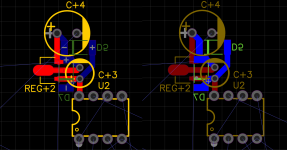
Which should be closer to the opamp pin:
1) the regulator output pin
2) the output capacitor pin
Which should be closer to the opamp pin:
1) the regulator output pin
2) the output capacitor pin
The cap.
Most of my boards now are SMD, but I still use THT electros, pots, switches, connectors and other large devices. I like to place components on both sides too.
Most of my boards now are SMD, but I still use THT electros, pots, switches, connectors and other large devices. I like to place components on both sides too.
As done in the pictures of the layout as the caps serve 2 masters here.This does raise another question.
Which should be closer to the opamp pin:
1) the regulator output pin
2) the output capacitor pin
I must be young enough to never have come across current noise in this context. Sounds like that's a good thing. 🙂 I appreciate the explanation. Thank you.Excess noise in resistors is also known as current noise, as the noise only shows up when there is current flowing through the resistors. It is most unfortunate that people call it that, as current noise is also short for equivalent input current noise, which is something completely different.
Tom
I'm sure they've been redesigned in modern processes as none of the equipment originally used to make them is around anymore. Those redesigns are not fun as everything about the chip needs to be designed in to the updated product, including various quirks and oddities that aren't in the spec sheet.78xx/79xx have evolved to a better version of themselves in time. From noisy LEGO like common parts to pretty good regulators. Point today is which one to pick from what brand as they differ.
My only warning about the older regulators is that one should be careful with ceramic capacitors around them. 100 nF ceramic is fine, but don't go crazy here. Especially, don't go crazy on the output side. I learned the hard way that the LM337 is not real fond of low-ESR capacitive loading that way. 🙂
Tom
Looking around for where I got the impression Excess noise can include more than Current noise (although the two terms are commonly used interchangeably).
However, the typical model is that current noise is pink (1/f), whereas Johnson noise is white.
AI Overview
Learn more…Opens in new tab
The formula for calculating the excess noise (also called flicker noise or 1/f noise) from temperature variation in a resistor is not a single, universally accepted equation, but a common representation involves the "Hooge constant" (αH), the number of charge carriers (N), and the current (I), expressed as: Vn = αH * (k * T / N) * I * (1/f), where "Vn" is the noise voltage spectral density, "k" is Boltzmann's constant, "T" is temperature in Kelvin, and "f" is the frequency.
Key points about this formula:
Basically, it looks like temperature variation of a resistor may change its Excess noise, even if the temperature variation is not caused by current flow.
Also:
...There is also a 1/f component in resistors with no direct current through them, likely due to temperature fluctuations modulating the resistance.
https://en.wikipedia.org/wiki/Flicker_noise#:~:text=1/f noise in current,temperature fluctuations modulating the resistance.
However, the typical model is that current noise is pink (1/f), whereas Johnson noise is white.
AI Overview
Learn more…Opens in new tab
The formula for calculating the excess noise (also called flicker noise or 1/f noise) from temperature variation in a resistor is not a single, universally accepted equation, but a common representation involves the "Hooge constant" (αH), the number of charge carriers (N), and the current (I), expressed as: Vn = αH * (k * T / N) * I * (1/f), where "Vn" is the noise voltage spectral density, "k" is Boltzmann's constant, "T" is temperature in Kelvin, and "f" is the frequency.
Key points about this formula:
- Hooge constant (αH): This constant varies depending on the material and manufacturing process of the resistor, typically considered to be around 2 x 10^-3.
- Temperature dependence: The noise is directly proportional to temperature (T).
- Frequency dependence: The noise power spectral density is inversely proportional to frequency (1/f), which is the characteristic of flicker noise.
- Complex nature of excess noise:
While this formula provides a basic understanding, the actual excess noise in a resistor can be influenced by various factors like surface imperfections, material properties, and geometry, making the calculation more complex in real-world scenarios.
Basically, it looks like temperature variation of a resistor may change its Excess noise, even if the temperature variation is not caused by current flow.
Also:
...There is also a 1/f component in resistors with no direct current through them, likely due to temperature fluctuations modulating the resistance.
https://en.wikipedia.org/wiki/Flicker_noise#:~:text=1/f noise in current,temperature fluctuations modulating the resistance.
My only warning about the older regulators is that one should be careful with ceramic capacitors around them. 100 nF ceramic is fine, but don't go crazy here. Especially, don't go crazy on the output side. I learned the hard way that the LM337 is not real fond of low-ESR capacitive loading that way. 🙂
Tom
I had the same issue with an LM317 used as a 1.8 V regulator, with only two 10 uF X5R capacitors as output decoupling. It was the digital core supply for the DIX4192 and SRC4392 in my valve DAC. The DAC worked fine, but sometimes there was a high-pitched beep coming from the PCB. It turned out that the LM317 sometimes oscillated, and the piezoelectric X5R capacitors then acted as piezotweeters. It was solved when I connected a 47 uF run-of-the-mill aluminium electrolytic capacitor in parallel with the X5R capacitors.
That's a fun one to debug. In my case I used an LM317/337 pair to power an opamp in a composite amp. Both had X7R on input and output. The THD+N of the amp was quite a bit worse than I'd expected. It turned out the LM337 was oscillating and injecting ~200 mV of RF on the negative supply rail, some of which made it to the amp output. The distortion analyzer interpreted this as +N so the THD+N ratio was degraded. Go figure...It turned out that the LM317 sometimes oscillated, and the piezoelectric X5R capacitors then acted as piezotweeters. It was solved when I connected a 47 uF run-of-the-mill aluminium electrolytic capacitor in parallel with the X5R capacitors.
I put in a plain Jane electrolytic and everything was fine.
Excess noise is simply the noise of a resistor that cannot be explained by thermal noise. Some resistor types have very high excess noise. Carbon composite types, for example. Other types have low excess noise. Most metal film types for example.Looking around for where I got the impression Excess noise can include more than Current noise (although the two terms are commonly used interchangeably).
While Susumu doesn't label the RG-series explicitly as "low excess noise", I've never measured higher than expected noise from the RG resistors.
The 300+ page compendium on resistors by Sandman, Simon, & Szwarc (2001) is a worthwhile read if you're interested in the peculiarities of resistors, resistive materials, and resistor manufacturing. I especially enjoyed the section, The Limits of Validity of Ohm's Law" 🙂
Tom
In a resistor, basically, you have thermal noise and random resistance variations.
It is very well possible that those random resistance variations are due to various different mechanisms; I don't know if they are, but I can't think of any reason why they couldn't be. When there is a DC current forced through the resistor, the random variations cause a noisy voltage drop across the resistor (and conversely, when there is a DC voltage applied across the resistor, a noisy current will flow through it). The resulting noise spectrum usually rolls off with approximately 10 dB/decade (1/f), but as far as I know, there is no fundamental reason why it has to be precisely that. When there is an AC current through the resistor, the resistance variations cause noise sidebands.
The thermal noise, on the other hand, is always there, it doesn't require any DC or AC supply. Two resistors with the same value and temperature have to produce equal amounts of noise, as otherwise, when you connect them, you would get a net power flow from the noisiest to the least noisy resistor, which would violate the second law of thermodynamics. Hence, without some sort of DC or AC bias, a carbon composite resistor and a metal foil resistor of the same value produce the same noise, just thermal noise.
So, I have a first draft of the layout.
Ignoring the rest of the layout and schematic for a moment. Is this a sensible way to do the ground when running 4 separate regulators?
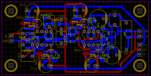
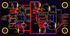
For clarity:
Signal ground
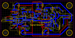
Power Ground
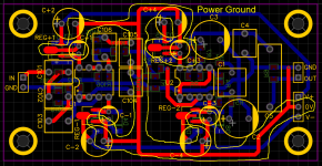
Would I be better running the ground from the top 2 regulators straight back to the 0V labeled PSU input header?
I also considered just using a ground plain for the power ground with a separate signal ground rail and a single jumper to connect the 2 at the PSU input header.
Ignoring the rest of the layout and schematic for a moment. Is this a sensible way to do the ground when running 4 separate regulators?


For clarity:
Signal ground

Power Ground

Would I be better running the ground from the top 2 regulators straight back to the 0V labeled PSU input header?
I also considered just using a ground plain for the power ground with a separate signal ground rail and a single jumper to connect the 2 at the PSU input header.
4-layer is about as low cost as 2-layer.
With 4-layers you can start to make some power and ground planes/fills. Those can help a lot if used carefully.
With 4-layers you can start to make some power and ground planes/fills. Those can help a lot if used carefully.
It is a mono board. It is recommendable to make it stereo in case your buddy has stereo. Dual mono does not make matters more easy I think. It makes you have to use many wires. It makes you think modular which is an incurable habit if you don't stop it. The preregulators could also be onboard and serve 2 channels. Truly gruesome is 2 channel boards, a DC board, a transformer board, an input board and an output board. This is modern designing and maybe one of the reasons the chinese are winning 😀
Never used 4 layer and wouldn't know how to do it but AFAIK there is no 2 GHz quad core CPU and 1666 MHz DDR4 RAM on that board. I think you will manage with just 2 layers to amplify the few tens of kHz but try not to have it amplify the noise from other devices that do have CPUs and transmitters. There are many excellent preamps with simple PCBs. Just keep it compact with short connections and as least as possible wiring. Use a metal box and try to include RCA connectors directly on the PCB. CRC with ferrite beads in the power lines before the regulators would be a nice addition. If you are able to do 4 layers then let nobody stop you.
Symmetry in cap positions is pleasing the eye and can be done without drawback. Please try to align parts and decide whether you want caps vertical or horizontal. Also, when using symmetric power supplies and JFET input opamps you might not need coupling caps at a few positions. You know that the best cap is no cap, right?
Last edited:
Successful routing of a two-layer board goes like this for me, for decades, with dominantly THT but also some SMT parts:
- Start with solid GND plane on top and bottom.
- Add stiching GND vias every 5..10mm or so, that is, hundreds of them literally, arranged in a grid.
- Generally, route traces on top layer in one preferred direction, and perpendicular to that on the bottom layer so that the GND never sees and interruption and doesn't form peninsulas, let alone full islands. Use the legs of the THT components to switch layers when feasible. Start with the supplies, using wide traces.
- Move the stiching vias if required, sometimes you have to remove a few to make room for the routing.
- OTOH, if you have longer traces on top and bottom that cross each other, place 4 vias in the 4 corners of the crossing to maintain GND continuity. Further, place vias along long traces on both sides.
- Try to avoid dense packing of parts to have enough room for routing. Spend most of the time on strategic parts placement, and don't be tempted to make visually nice arrangements. The electrons don't care.
That is my next step.It is a mono board. It is recommendable to make it stereo in case your buddy has stereo. Dual mono does not make matters more easy I think. It makes you have to use many wires. It makes you think modular which is an incurable habit if you don't stop it. The preregulators could also be onboard and serve 2 channels. Truly gruesome is 2 channel boards, a DC board, a transformer board, an input board and an output board. This is modern designing and maybe one of the reasons the chinese are winning
Step one was figure out a decent grounding scheme for the regulators on a 1 channel board.
Step two is to try and do it in stereo.
Since nobody seems to think the design is terrible. I think I will proceed with something along the lines of what I have.
@jean-paul ,Will do... it'll probably be a mostly digital board with SMT parts, but using the exact same ideas... and it was really required to pass EMC test
Curious how a 4 layer phono board looks. I never used 4 layers nor ground planes for a phono preamp and never seen any either. I grew up without design software and only single layer boards. About all phono preamps of the phono era were single layer and TH then. Main thing I notice besides their still fine performance is susceptibility to today's EMI.
I think Sadface draws by hand and uses no autorouting.
Sadface, it is not too important what others think. There are hardwired preamps that (contrary to expectations) function OK. Just make a complete design and then ask for technical advice.
BTW I meant symmetry of channels with a central power connector and inputs and outputs grouped (but away from each other), of course place parts strategically best.
Last edited:
- Home
- Amplifiers
- Power Supplies
- Regulators right beside OPamps pins
