this is good .....mooly
you know from a funny point of view ......
the dutch did again !!!!!
1- he made two more people construct
2- one of them constructed the other one also updated the circuit
3- there is two people at least to guaranty that there is no power supply issue
4- he has now a lot of real life wave forms no simulators
5-and he is ready to use a very critical tip "componets selection"
to my understanding dutch is a happy lucky SOB ha ha ha ha ha
i wish this kind of development was happening to my threads also .....
all the best people !!!!!
Mooly said:That suggests you could easily reduce the current draw which would be very beneficial to reducing ripple on the supply.
What do you think ?
The amplifier has something to be said for it as it stands. It has a low output impedance for class A. Running as hot as it is probably contributes to its not unimpressive if somewhat unnecessary bandwidth.
Since, however, it has a load of electrolytics in the signal path, it seems to me that this is more by accident than design.
So, can I ask again, is there any philosophy to the design of this amplifier, or is it just a bunch of components thrown together more in hope than good judgement?
w
Hi Wakibaki,
Actually "Where did the design come from ? ".
I was having some more thoughts on this -- as you do--.
GD has come up with this amp, built it and been bowled over by the quality. Great -- that is what it's all about.
Agree about the bandwidth, I suppose more so because it's so ill defined.
Which brings me to my "thought". The BC550 and 2N3055 connected as a darlington pair. I am sure a resistor across the B-E junction of the 2N3055 would help speed things up a bit. Might try that for curiosity ! The effect of "hole storage" and all that, due to the Bjt being a minority carrier device.
And back to the efficiency thing. If we say a single ended resistive loaded class A output is 12.5% efficient, 3 to 4 watts power draw seems a bit OTT for a headphone amp.
But thats just my opinion, and as Carlos said earlier, I too wish more folks would experiment a bit and not rely on simulators. You learn far more that way.
Have you had any better luck with the hum problem GD. 🙂
Wakibaki 😀 😀 And as to "throwing a bunch of components in the air and seeing how they land". You've never worked on a P-----S. S.M.P.S. then. All the big companies do it, it's what keeps service departments busy 😉
And if GD suspected it before, I am sure he now knows. We're all a bit mad round here. 😀
Mooly said:Hi Wakibaki,
Actually "Where did the design come from ? ".
Okay - where DID it come from?
After asking some mates if they can explain to me how an amplifier work they all laughed and directed me to a few online articles on basic solid-state amplification. I studied the concepts and basic designs and came up with a crude 2 transistor amplifier that barely worked.
This then quickly evolved when I read more about Darlington pairs. I made an amp similar to the current one but with three 3055's > Input and Darlington pair.
Trschrama from here saw the circuit and helped me tweak it a bit also adding the bootstrap circuit.
A professor friend of mine also chipped in with some better values on caps etc here and there.
See the original thread here: http://www.diyaudio.com/forums/showthread.php?s=&threadid=124673&highlight=
D
PS - I did install that .1uF cap between collector and "correct" ground... helps alot and sound did improve.
Also made a single ground point (star ground) - things did improve a little but the hum is still there with the mains transformer. C'est la vie... I'll wait for the regulators to arrive.
D
Also made a single ground point (star ground) - things did improve a little but the hum is still there with the mains transformer. C'est la vie... I'll wait for the regulators to arrive.
D
Hello GD,
It's good your still with us. Further thoughts as per my earlier post on the slow turn off of the output transistor.
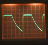
These pics are awful, thats my cheapo camera not your circuit oscillating or anything but see what you think to this.
Back to the TIP3055 ( you forget how slow these things really are 🙂 ). This is at 100 khz.
It's good your still with us. Further thoughts as per my earlier post on the slow turn off of the output transistor.
These pics are awful, thats my cheapo camera not your circuit oscillating or anything but see what you think to this.
Back to the TIP3055 ( you forget how slow these things really are 🙂 ). This is at 100 khz.
Attachments
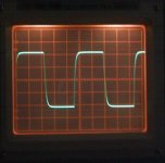
And with the addition of a 27 ohm across the B-E. Look at that !!
Try whatever you have as long as it's below about 150 ohms. Don't go below 27 ohms, as it's pushing the driver a bit, 47 ohm would be a good choice. It would be interesting to see if it audibly effects the sound. Proof of "Hole storage effects" in Bjt's.
Try whatever you have as long as it's below about 150 ohms. Don't go below 27 ohms, as it's pushing the driver a bit, 47 ohm would be a good choice. It would be interesting to see if it audibly effects the sound. Proof of "Hole storage effects" in Bjt's.
Attachments
Hey Mooly! Thats a great improvement there - I'll try it.
The amp really baffles me... it sound so perfect. Everything is focussed and coherent with a vivid presentation. Beats the previous "setup" where I drove my headphones directly from my amps speaker terminals (thats 100 watts per channel!!)
One other thing that I have noticed is that the "thermal noise" is much quieter now with that little cap on the collector.
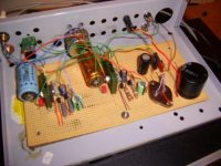
See pics of my latest "upgrade" - notice all the green ground wires everywhere leading to a single ground point.
D
The amp really baffles me... it sound so perfect. Everything is focussed and coherent with a vivid presentation. Beats the previous "setup" where I drove my headphones directly from my amps speaker terminals (thats 100 watts per channel!!)
One other thing that I have noticed is that the "thermal noise" is much quieter now with that little cap on the collector.
See pics of my latest "upgrade" - notice all the green ground wires everywhere leading to a single ground point.
D
Attachments
Another thing... as we are on the topic of "anything will work"... the actual power transistors used is not 3055's but Motorola SJE5300's (TO220).
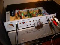
Pictured here is the fashionable front of the amp complete with a polished volume knob from an old QUAD 33 pre-amp. 😀
D
Pictured here is the fashionable front of the amp complete with a polished volume knob from an old QUAD 33 pre-amp. 😀
D
Attachments
Hi GD,
I am sure it does sound "perfect". This kind of thing really does highlight that we don't really fully understand why we like some designs over others. Of course the same applies to power amps as well. Technical perfection (whatever we define that as) counts for nothing if you don't really like what you hear.
Your construction -- is that veroboard or is it all hard wired underneath, you know point to point wiring ?
The technical perfection thing... mmm... I used to own a set of QUAD mkII tube amps and where shocked when I saw there output response were actually horrable! Well, the sound bloody good to my ears...
Yes - that 3055 turned on its back is the capacitance multiplier.
I used Veroboard - hate the stuff but is does make for a neat prototype doesnt it?
I have ordered some "barrier strips" or tag strips to do furture prototyping on.
D
Yes - that 3055 turned on its back is the capacitance multiplier.
I used Veroboard - hate the stuff but is does make for a neat prototype doesnt it?
I have ordered some "barrier strips" or tag strips to do furture prototyping on.
D
Can you check if the hum stays if you use only one channel...?
I have a small class A headphone amp, that is an absolute bitch to get quiet with two channels....
I can set it to a quit/ish point, but after some playing that point drifts and needs readjustment...
With useing only one channel, the problem is not there...
Also just a small prototype, I think I drawed the PCB... veroboard is so expensive these days...PCB is cheap.
Nordic said:With useing only one channel, the problem is not there...
Easy to fix, make it dual mono. 😀
If it's the multiplier I posted back at post #14 try this.
You can make a zener from a reverse biased transistor B-E junction. If the multiplier is as the circuit you will not do any harm.
Connect the emmiter of a transistor to the positive end of the 100 mfd cap and the base to the negative end. Use an old power transistor for this. I have not tried this and it's years since I connected a transistor like this. It was the recognised way of producing a white noise source but don't worry about that. If you try it the output voltage will fall to around 7 or 8 volts but the BIG question is does it still hum ? or not ?
I think I have remembered that correctly, if I have the voltage across the 100 mfd cap will be 8 volts or so.
Mooly said:It was the recognised way of producing a white noise source but don't worry about that. If you try it the output voltage will fall to around 7 or 8 volts but the BIG question is does it still hum ? or not ?
I think I have remembered that correctly, if I have the voltage across the 100 mfd cap will be 8 volts or so.
Will most certainly try it!
The resistor across B-E on the OP transistor made a suttle yet prominent improvment on the sound! Things is just getting better and better. Thumbs up!
D
Andre Visser said:
Easy to fix, make it dual mono. 😀
Its already dual mono... he-he! or is it? No wait... using a single cap multiplier... mmm...
D
It's worth trying, the DC voltage (the rail voltage) will be low but it may help prove whats going on hum wise.
Old Quads--- Very nice 🙂
Old Quads--- Very nice 🙂
GlidingDutchman said:
Its already dual mono... he-he! or is it? No wait... using a single cap multiplier... mmm...
D
You need two PSU's. 😀
Did you try to connect only one channel and see if it still hum, as Nordic suggested?
- Status
- Not open for further replies.
- Home
- Amplifiers
- Solid State
- Regulated DC PSU - Plain and simple please?