Hi there
Sorry for this dumb question but I need some pointers on a simple, regulated PSU that produces 0 - 12v DC.
It is a for a single ended amp that I built but a standard bridge rectifier induces too much buzz in the system
Thanx
Dewald
Sorry for this dumb question but I need some pointers on a simple, regulated PSU that produces 0 - 12v DC.
It is a for a single ended amp that I built but a standard bridge rectifier induces too much buzz in the system
Thanx
Dewald
That symptom does not sound like it's the fault of the rectifier. I would more likely expect a wiring/construction fault.GlidingDutchman said:.......I need some pointers on a simple, regulated PSU that produces 0 - 12v DC.
It is a for a single ended amp that I built but a standard bridge rectifier induces too much buzz in the system.......
Re: Re: Regulated DC PSU - Plain and simple please?
No, I dont think so as the amplifier circuit works just fine on the makeshift PSU from a PC and from the battery.
D
Mooley, I think a 15VA to 25VA system would suffice.
D
AndrewT said:That symptom does not sound like it's the fault of the rectifier. I would more likely expect a wiring/construction fault.
No, I dont think so as the amplifier circuit works just fine on the makeshift PSU from a PC and from the battery.
D
Mooley, I think a 15VA to 25VA system would suffice.
D
Hello GD, what are you using for filtering of the rectified DC. If you don't have a ground issue, as AndrewT implied, then you probably need more capacitance in your supply filter. Or maybe a CLC type filter.
Peace,
Dave
Peace,
Dave
dave_gerecke said:Hello GD, what are you using for filtering of the rectified DC. If you don't have a ground issue, as AndrewT implied, then you probably need more capacitance in your supply filter. Or maybe a CLC type filter.
Peace,
Dave
Hi Dave
I have a single 63v - 10000uF cap on the supply rails as well as a propper rectifier bridge but the 50Hz buzz is terrable. When I switch to the old PC power supply the amp is dead quiet.
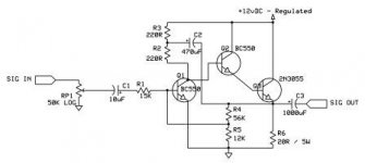
What regulator transistors would you recommend? I think it would be worth while to do a popper PSU for this amp... see attached.
Attachments
Hi Dewald...
It looks like a class A output... drawing about 0.6A
A start would be to look at doing a capacitance multiplier.... have a look at Rod Elliot's site...
Alternatively you could look at a fixed linear regulator like 7812 in TO220 package, good for about 1.5A up to 10V drop from supply rails...
Or with slightly better noise figures an adjustable reg like the LM317.
Download datasheets for both from google an read through it...
The regulated supply I posted on the Chipamp section recently is a step up, and with a nice 12VAC transformer a 12V zener and a hetsink that can deal with the 3W of dissipation, it should work sweet. It is a combination of a voltage regulator and capacitance multiplier...
Dewald's 15 to 25VA looks like enough headroom...
That circuit has an intrinsicaly low noise rejection, so you need a good supply. And will be pretty hard to get buzz free while shareing a transformer between channels
Hello Dewald, Andre Visser brings up a good point. If you are working the transformer too hard, this can contribute noise. It doesn't sound like you need more capacitance. Perhaps as Andre suggested, you should check the trafo. You could also go overboard and move the PS section into a separate case. This would tell you if you have an isolation issue. If you do decide to go with a regulated supply, for the voltage and VA rating you list, you should be able to use an LM317 or LT1085 regulator chip. You could build a regulator from discreet components also. If you take that route, I would use a 2N3055, easy to get, cheap, and handles a good amount of power.
Peace,
Dave
P.S. How is your ground setup? If possible, go with a star ground format, and isolate your safety ground from your circuit ground with a bridge rectifier or NTC, ala Nelson Pass Zen amps.
Peace,
Dave
P.S. How is your ground setup? If possible, go with a star ground format, and isolate your safety ground from your circuit ground with a bridge rectifier or NTC, ala Nelson Pass Zen amps.
Guys
The transfo puts out 14.5V DC (Internal bridge rectifier) - this is a stand-alone "transformer" that I use in my workshop to power all kinds of stuff...
The ground scheme is not the culprit as the transformers windings are totally isolated.
I just think a simple regulator scheme will do the trick - dont you?
You say a 3055 ss? I have plenty of them in stock - how should I go about building a regulator?
D
Hello Dewald, take a look at this website. They explain how to design a power supply using a pass transistor to control the voltage. If you still have questions, drop another post.
http://www.tpub.com/neets/book7/27k.htm
Peace,
Dave
http://www.tpub.com/neets/book7/27k.htm
Peace,
Dave
Since you only have 2.5V (did you measure 14.5V under load condition?) above your required 12V output, I would go for the LT1085 regulator.
Try connecting ground to the trafo body.
I would suggest the use of a capacitance multiplier. U don't need a regulated PSU for a power amp.
Gajanan Phadte
I would suggest the use of a capacitance multiplier. U don't need a regulated PSU for a power amp.
Gajanan Phadte
Hi,
A lot of good suggestions here. Only having 14/15 volts to play with rules out a series regulator unless you opt for a lower voltage, say 10 volts. I would go with a simple capacitance multiplier as others have advised, it will at least prove that is the problem.
A lot of good suggestions here. Only having 14/15 volts to play with rules out a series regulator unless you opt for a lower voltage, say 10 volts. I would go with a simple capacitance multiplier as others have advised, it will at least prove that is the problem.
Attachments
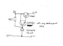
It's what I posted diagram of. It relies on the HFe or gain of the transistors to make the capacitor "appear" much larger than it really is. The value of the cap is "multiplied" by the combined current gains of the two transistors. You could make it regulated by the addition of a zener across the cap. Try a 10 volt zener. You still need the main smoothing cap across the bridge and add a small value - say 100 mfd - across the output.
Seems pretty simple really.
With most mains-rectified power supplies, there's always some ripple on the line, especially with *only* 10000 uf.
Since it's a Class A amp (zero PSRR) you will definately hear the hum even with MUCH more capacitance. A class A or especially A-B amp with a differential LTP input would be much less sensitive to the ripple.
Also you mention a 12V transfomer right? In that case, unloaded off the rectifier you should get about peak 17-19V DC depending on your transformer. A regulator would work good as long as the transformer can hold the voltage under high load.
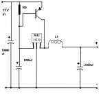
Since a 7812 regulator may get hot, use a Power PNP transistor (on heatsink) to "boost" the 7812 by connecting its input to the base, and the collector to its output, and the emitter to the + rail. Then I'd still add more capacitance + inductor coil of a few turns around a small toroid core after the regulator to help filter even more. A 0.5ohm power resistor can also be used in place of the inductor.
Even better is if you want to use a capacitance multiplier WITH the regulator
Another option from this (IMO is much better) is to use a PC SMPS + a 0.5ohm resistor with your 10000uf cap. SMPS produces no 50 or 60hz ripple, but the HF ripple of a SMPS is much easier to filter.
With most mains-rectified power supplies, there's always some ripple on the line, especially with *only* 10000 uf.
Since it's a Class A amp (zero PSRR) you will definately hear the hum even with MUCH more capacitance. A class A or especially A-B amp with a differential LTP input would be much less sensitive to the ripple.
Also you mention a 12V transfomer right? In that case, unloaded off the rectifier you should get about peak 17-19V DC depending on your transformer. A regulator would work good as long as the transformer can hold the voltage under high load.
Since a 7812 regulator may get hot, use a Power PNP transistor (on heatsink) to "boost" the 7812 by connecting its input to the base, and the collector to its output, and the emitter to the + rail. Then I'd still add more capacitance + inductor coil of a few turns around a small toroid core after the regulator to help filter even more. A 0.5ohm power resistor can also be used in place of the inductor.
Even better is if you want to use a capacitance multiplier WITH the regulator
Another option from this (IMO is much better) is to use a PC SMPS + a 0.5ohm resistor with your 10000uf cap. SMPS produces no 50 or 60hz ripple, but the HF ripple of a SMPS is much easier to filter.
Attachments
http://sound.westhost.com/project15.htm
A capacitance multiplier multiplies the capacity of a cap(s) with the gain of a connected transistor...
A capacitance multiplier multiplies the capacity of a cap(s) with the gain of a connected transistor...
Well
I built the circuit as described by Mooly. It does help to smooth things out but now when I connected the h-amp to my phonostage I get hum again.
Here is a pic of the build on veroboard:
I built the circuit as described by Mooly. It does help to smooth things out but now when I connected the h-amp to my phonostage I get hum again.
Here is a pic of the build on veroboard:
An externally hosted image should be here but it was not working when we last tested it.
Hello
I have a question that is somehow related to this thread:
Is it a good idea to use a capacitance multiplier for a class AB amp of about 80W 8 ohm/120W 4 ohm. Or it will wreak the sound?
I have a question that is somehow related to this thread:
Is it a good idea to use a capacitance multiplier for a class AB amp of about 80W 8 ohm/120W 4 ohm. Or it will wreak the sound?
- Status
- Not open for further replies.
- Home
- Amplifiers
- Solid State
- Regulated DC PSU - Plain and simple please?