Hi guys,
I have been looking around the web for a long time for a schematic for a dual-rail tracking power supply. I would like it somewhat scalable and with something like 40-50 V per rail and maybe 4-5 A per rail. I want voltage adjust and current adjust so that I may run constant voltage or constant current. It would be most useful for testing my projects and may then be used from anything to a small OP-amp based pre to a power amplifier like an Aleph (and I think I have the dissipation issues resolved).
I have found nothing. Does anybody have something like this? I know Elektor has had many projects but I have none of those magazines.
Thanks/UrSv
PS. Single rail is no problem but tracking dual-rail is.
not that this really helps you...
I would like to see some of the single rail designs. I know I should look it up myself but it would still be nice to see what you have found.
I would like to see some of the single rail designs. I know I should look it up myself but it would still be nice to see what you have found.
Hello,
I mean the easiest test supply would be just a transformer, caps and a variac. But not everybody has this lying around.
What about a capacitance multiplier with adjustable voltage?
A lot of adjustable power supplies (single and dual rail) you can find in datasheet of for example National Semiconductor and especially Linear Technology.
The LT1038 for example would work for up to 10A but at such high currents power dissipation becomes important.
I don´t know what you are looking for Lligior but if you´re looking for an adjustable test supply (not for audio) I´d use the old-fashioned LM723. I built a few PSU´s with that chip and they´re just perfect for test/repair-purposes.
Jens
Try Burr-Brown's OPA548 and OPA549. They are power OP's with a current adjust pin. Very nice and easy to use.
/Marcus
/Marcus
I just bought another one today
the problem of <em> make vs buy </em> -- it's cheaper to buy a used HP, Lambda or Sorensen in this range. EBay now has a power supply category -- search under Business & Industrial/Electrical Equipment. There are always a lot of low noise analog supplies.
I just bought another beefy HP supply today. One which falls within your range is the HP6129C -- actually a quasi-complementary voltage amplifier -- requires you to build a programer, but this is easy with a PIC or AVR -- here's one which I own:<p>http://www.tech-diy.com/beast.htm
Not long ago i put together a low current (1.2A) dual 0-30V supply with some adjustable regulators and some salvaged panel meters. This will work for active crossevers and preamps but its not exactly a workhorse. No good for output stage testing, and it would be nice to be able to test without having a pile of xformers laying around. So my thinking is if I can set a schematic that uses at least some parts I have it might be worth it to build one. More or less a feasability study if you will.
(edit time ran out)
joensd
just looked at the data sheet LT1038 seems pretty good. seems like it would be easier to use a fan on the heatsink than construct their scr efficieny circuit. May even be able to use two of them to get a current limiter too. Thanks this is almost the same circuit I just built. If only I had seen this first... but this will take some serious heatsinks. Just an oppertunity to try out to-3 package
🙂
You really need to look at the diy opamps article by Nelson Pass. It has some great info on building opamps from transistors. You can use transistors as large as you need. I have built an opamp with a 1600W dissipation rating using this (and it only cost about $30).
I am also building a bench power supply. It is positve and negative 0-30V 0-10A. It uses 8 TO-3 power transistors on a huge heatsink. I have not finished it yet but what I have tested looks promising. It shouldn't be too hard to modify for your needs. In about two weeks I should be able to tell you if it works or not.
http://gemini.tntech.edu/~dlh5678/psu.html
It consists of 3 boards which have not been properly documented yet.
http://gemini.tntech.edu/~dlh5678/psupos.pdf
http://gemini.tntech.edu/~dlh5678/psuneg.pdf
This has pot connections and controls a character lcd panel displaying voltages and currents. The other boards also connect to this.
http://gemini.tntech.edu/~dlh5678/psumeter.pdf
I also considered those huge opamps. They are expensive, and would probably smoke. You could be talking about 500W-1KW dissipation at a low voltage setting.
Darrell Harmon
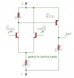
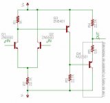
And now the negative supply opamp.
Don't trust the resistor values. They are best found by trial and error. Read diy opamps for an understanding of how this works.
Set the positive amp up as either a buffer of a positive gain, and set up the negative opamp as an inverting amp. I set mine up where +10V would give full scale output. I did this so I could use cheap opamps for everything else. I also added current sensing resistors and a difference amp to sense current. If current goes above the preset limit another opamp pulls down the voltage setting.
This thing will need some serious heatsinks, and probably 4 output transistors in parallel. I chose the MJ2501 because it is cheap. Mouser sells it for about $3. It is a PNP darlington in TO-3 and is rated for 200W.
Depending on resistor values this thing will have some offset and you might want to enclose it in the feedback look of another opamp.
Attachments
Thanks a lot for the suggestions.
I found some single-rail at www.epanorama.net and many other places. I will check what I have.
It is easy to find a PSU but dual-rail with current adjustment has proved hard. The search continues and EBAY is next...
Thanks/UrSv
I found some single-rail at www.epanorama.net and many other places. I will check what I have.
It is easy to find a PSU but dual-rail with current adjustment has proved hard. The search continues and EBAY is next...
Thanks/UrSv
Have you checked Mark Hennessy site. It's work in progress, +-18V, 2A (it's a "little" less that you are looking for), no detailed schematics, but you might ask him for help. He's a forum's member.
Thanks for the Henessy link.
Yes I have checked it. Unfortunately it is not quite finished and I don't have the full schematic. Maybe one day I will e-mail him...
/UrSv
Yes I have checked it. Unfortunately it is not quite finished and I don't have the full schematic. Maybe one day I will e-mail him...
/UrSv
dlharmon,
The problem with a regulated PSU is very often that the dissipation is too high. In my case if I have 60 VDC before regulation and need an output of 25 V at 4 A this would give me 35 * 4 * 2 = 280 W of wasted power which needs to be dissipated as it is too much.
/UrSv
The problem with a regulated PSU is very often that the dissipation is too high. In my case if I have 60 VDC before regulation and need an output of 25 V at 4 A this would give me 35 * 4 * 2 = 280 W of wasted power which needs to be dissipated as it is too much.
/UrSv
UrSv said:dlharmon,
The problem with a regulated PSU is very often that the dissipation is too high. In my case if I have 60 VDC before regulation and need an output of 25 V at 4 A this would give me 35 * 4 * 2 = 280 W of wasted power which needs to be dissipated as it is too much.
/UrSv
I saw a quite nice solution to that problem over 20 years ago
in a german electronics magazine. The regulated supply was
preceeded by a switched supply which attempted to keep a
constant voltage drop over the regulator. I don't know how
well it handled load transients though. This was a single supply,
but I see no immediate problem with using this idea for a dual
one.
Same kind of thing I had in mind. I saw something in ELV (ELW?) in Germany way back. They had many smaller transformers of say 2* 12 VAC and connected them in series and used an array of relays to connect the output that had the lowest possible voltage so for 5 VDC out they would have the first 12 VAC winding connected and for 40 VDC out they would have the 36 VAC winding connected giving a maximum of some 15 V of drop across the regulator. The higher the output current the lower the individual transformer voltage to reduce dissipation. This is the approach I was planning. A bunch of 12 VAC transformers I probably have or can get really cheap.
/UrSv
/UrSv
UrSv said:dlharmon,
The problem with a regulated PSU is very often that the dissipation is too high. In my case if I have 60 VDC before regulation and need an output of 25 V at 4 A this would give me 35 * 4 * 2 = 280 W of wasted power which needs to be dissipated as it is too much.
/UrSv
You could use a variac before the input to keep this under control, but it would need to be a big one. Another option would be use 12VCT transformers in series and switch to the appropriate tap. I find that 300W of heat from a bench ps is not too bad, it just needs a big heatsink. Of course your ps would put out twice the heat of mine. Another options would be to use scr's instead of a normal bridge, and control voltage by where in the cycle they are on. It would cause some electrical noise, but it would work. A good book with a whole chapter on power supplies is Art Of Electronics by Hill and Horrowitz. It is expensive, and you might want to try to find it at a library.
If you check out the schematic for the positive or negative output boards I posted earlier you can see how I did the constant current.
I think I have about $150 in my power supply now. That was possible only because of surplus parts. You might really consider buying one. I chose to build for the learning experience. I had built a Pass Son Of Zen amp and didn't like the 600W of heat, so I decided I would make a power supply out of it.
I was going to tell you where to get some cheap heatsinks and transformers, but I noticed where you are and didn't think you would want to pay to ship 30Kg of heatsinks and transformers from the US.
Darrell Harmon
a tube PS using 807's
a pretty old Genrad lab amplifier, could be pressed into service for a regulated HV supply:
here's the link: http://cgi.ebay.com/ws/eBayISAPI.dll?ViewItem&item=1783116852&rd=1
http://ebay1.ipixmedia.com/abc/M28/_EBAY_d525b0a90516d9b0dcbc322769bb3372/i-3_B_L.JPG
a pretty old Genrad lab amplifier, could be pressed into service for a regulated HV supply:
here's the link: http://cgi.ebay.com/ws/eBayISAPI.dll?ViewItem&item=1783116852&rd=1
http://ebay1.ipixmedia.com/abc/M28/_EBAY_d525b0a90516d9b0dcbc322769bb3372/i-3_B_L.JPG
Hi all!Have you checked Mark Hennessy site. It's work in progress, +-18V, 2A (it's a "little" less that you are looking for), no detailed schematics, but you might ask him for help. He's a forum's member.
Just noticed this thread... Thought I'd let you know that "my" topology won't scale up to the voltage levels you require unless you use high-voltage op-amps.
The power supply has been in use for well over a year, and has served me well. You're right - it is a 'work in progress', but there isn't much left to do - only a few trivial details. I haven't bothered to finish the schematics, but when I do they will appear on the site.
I quite enjoy building power supplies, and have lots of plans involving my massive collection of mains transformers and heatsinks! Watch this space - the next project will be exactly as you request, but it won't happen for a long time... In the meantime, I'm very happy to help if I can

- Status
- Not open for further replies.
- Home
- Design & Build
- Parts
- Regulated bench PSU