dlharmon said:
1. I am planning to use an opamp to add about 5V to the desired regulated output voltage for the input to the prereg. (ripple at 10A was about 2 volts).
[snip]Darrell Harmon
Right. So, for a say 30V output, this opamp will have at one of its input 30+5=35V as reference, output to drive the mosfet another 5 or so.. All powered from a ground-centered +/- 15VDC. I told you, you can get very creative here.
Jan Didden
I'am interested in building such regulated bench PSU.
Will there be a schematic available when finished?
bye,
mario
Will there be a schematic available when finished?
bye,
mario
I finally tested some hardware this weekend. It is not quite finished, but I got a good start. I didn't have any P fets so I substituted a PNP transistor. It worked just as in spice. I could not test at much current because the PNP was too low current. The RC setup on the input worked well to bring the voltage up slowly. I had the thing running with a series light bulb and it didn't get nearly as bright as usual. The regulation worked well, and I couldn't feel any heat on the switch transistor's heatsink. Any suggestions for fets? My supply is 10A, and I need a P channel for the + supply and a N channel for the - supply. It results in 80A pulses in spice with the transformers set up with 0.15 ohm series resitance. The rectifed AC has peaks of about 35V. It is nearly the same as the schematic I posted earlier except the comparator's negative supply is connected to -15V instead of ground, the N channel fets source is tied to -15V and there are some zeners and resistors to keep gate voltages in acceptable range. If anyone wants to see the new schematics just ask me.
Darrell Harmon.
Darrell Harmon.
A few months ago I bought a large studio flash that had a few problems to fix. I opened it up and was interested in its cap charger. There were no inductors or transformers, just a voltage tripler on the AC line. There were no power resistors and the thing really doesn't produce heat. It apparently is set up similar to the way I designed that preregulator. The amazing part is that it can charge 8000uF to 450V in 2 seconds and do this repeatedly for hundreds of cycles. It doesn't get hot except for of course the flashtube. The problems had nothing to do with the power supply. It was just a few bad connections. At that time I was clueless as to how it works, but using it this weekend I thought of the ps and realized how it had to work.
I just thought I would mention that as an example that things like this might actually get some use in commercial products.
I bought another one later that had the same tripler, but instead charged the caps through a 300W power resistor and controlled the power level by switching caps in and out with relays. The first one is much smaller and works much better.
Darrell Harmon
Variac and transformer...
For high poer stuff, the only way to go is variac and transformer...
Scrounge around for a 20A variac... ...they can be found. A 1 to 3 KVA 480 - 220 transformer (or 440/220 - 220/110) control transfomer can be used for isolation/dual rails. Caps, well, them's can be hard, but can be found at surplus. More supply than you'll ever need... ...unless you're like me 🙂
Oh, yeah, FYI When you plug it in start with the variac at the 0 volt output setting, I welded a 120V plug into the recepticle once 🙂
For performance... ...this will give you a rough idea...I have a 20 Amp variac, a 1.5 KVA X-fmr, full wave bridge rectifiers, filtered with a pair of 66,000 uf 75WVDC caps. Will supply from a few volts to around +-85 VDC. I've tested it at 600Watts per rail, with ripple around .75V P-P. I don't remember what the regulation was like, but it seems to me it was about 10 or 12 volts drop at 600W.
As far as current limiting... ...This is a trick I learned from my father, and use very often. Just use some 120V light bulbs in series with the power rail. I have a pair of 120V 60 watt light bulbs I switch into the rails. They'll allow a an amp or two, and have some foldback current limiting (resistance goes up as they light up). Change the watteage for different current limit levels.
-dan
Re: Variac and transformer...
That is quite useful. In fact it is what I do now. I just want something more precise.😀
My pcb's came so more testing will occur this weekend. That is if I don't start working on the flashmeter.
Darrell Harmon
dkemppai said:For high poer stuff, the only way to go is variac and transformer...
Scrounge around for a 20A variac... ...they can be found. A 1 to 3 KVA 480 - 220 transformer (or 440/220 - 220/110) control transfomer can be used for isolation/dual rails. Caps, well, them's can be hard, but can be found at surplus. More supply than you'll ever need... ...unless you're like me 🙂
Oh, yeah, FYI When you plug it in start with the variac at the 0 volt output setting, I welded a 120V plug into the recepticle once 🙂
For performance... ...this will give you a rough idea...I have a 20 Amp variac, a 1.5 KVA X-fmr, full wave bridge rectifiers, filtered with a pair of 66,000 uf 75WVDC caps. Will supply from a few volts to around +-85 VDC. I've tested it at 600Watts per rail, with ripple around .75V P-P. I don't remember what the regulation was like, but it seems to me it was about 10 or 12 volts drop at 600W.
As far as current limiting... ...This is a trick I learned from my father, and use very often. Just use some 120V light bulbs in series with the power rail. I have a pair of 120V 60 watt light bulbs I switch into the rails. They'll allow a an amp or two, and have some foldback current limiting (resistance goes up as they light up). Change the watteage for different current limit levels.
-dan
That is quite useful. In fact it is what I do now. I just want something more precise.😀
My pcb's came so more testing will occur this weekend. That is if I don't start working on the flashmeter.
Darrell Harmon
this really works:
I needed separate B+ and C- supplies that I could control with a microprocessor -- this design works by regulating the ground return -- making it a lot easier to work with. The "sense resistor" adjusts the gain of the control loop. The DAC acts as a variable reference.
You could also make the regulator "track" but I needed independence.
Attachments
I didn't get much done this weekend because a package of pcb's showed up from Olimex, and I just had to solder up and test my flashmeter. Hopefully I will get more done next weekend.
I did also solder up my controller and output boards, but have not tested them.
Darrell Harmon
I did also solder up my controller and output boards, but have not tested them.
Darrell Harmon
I just ordered a pair of huge fets. They are Fairchild RFG70N06. They are 60V 70A 0.01 ohm on resistance. They should work well and were only $3.20 from Mouser. They are both going to be N channel because I couldn't find a P channel with a high current rating. This will complicate the electronics some.
Darrell Harmon
Darrell Harmon
dlharmon said:[snip]They are both going to be N channel because I couldn't find a P channel with a high current rating. This will complicate the electronics some.
Darrell Harmon
Actually, Darrell, it's making it easier. Only one board layout, just 2 copies. Two identical supplies, connected at the common "ground" point.😉
Jan Didden
It seems I will also do two identical supplies as I can not find a got schematic for a tracking supply. On the other hand that means that I can, as Jan says, just connect them with ground on the positive supply to plus on the negative supply when I need dual and in parallell when I need double current single rail.
/UrSv
/UrSv
for a tracking supply/P Channel FETs
you have one reference for the "+" side, the reference for the "-" side is derived from a simple voltage divider on the output of the "+" side. <em>Ergo hoc</em> any change in the "+" voltage will become the new reference for the "-" side.
P-Channel HEXFET's -- there are some high power devices -- you can parallel devices but make sure to read International Rectifier's application note on this -- in one "negative" supply I built I just used an NPN transistor in the ground return -- I've already posted the schematic. -- I use a BU208a -- of which I have plenty if you need them.
Reference
True but after thinking I suddenly quite like the idea of being able to parallell connect my supplies for double the current. It seems I will stick with that...
/UrSv
True but after thinking I suddenly quite like the idea of being able to parallell connect my supplies for double the current. It seems I will stick with that...
/UrSv
Starting next Thursday I will not be able to post for about a month due to really slow intenet access at home, but I will have plenty of time to finish and test my power supply since I will not be having deal with all this college stuff. (I am majoring in EE, but its stuff like Differential Equations and Phyics that consume my time)
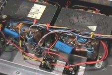
One comment on why I am doing things the way I am doing them: I am using 48VCT transformers since I got them cheap. I want 30V 10A, so I am using the CT as ground. It is not worth new transformers for seperate supplies. I got mine for $10 each 500VA EI.
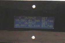
I did my front panel last weekend. It is plexiglass painted black on the rear except for the LCD and control labels which I masked before I painted it. It worked great. I hope to post pictures sometime. It has a LCD in the center with a pair of binding posts and a voltage and current control above them to the sides of the LCD. On the left side there are switches for soft power (set to 0V all outs) current tracking and voltage tracking. The real power switch is on the rear by the power inlet.
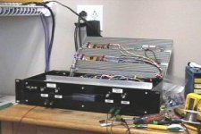
I am using amp MTA connectors for all of the low current internal wiring. They work nicely. I have a spool of 500feet of old cable containing 6 22awg stranded twisted pairs. I am using the pairs to wire everthing low current. The control board had about 40 wires connected to it, but with the connectors and bundling it looks good. The high current things are soldered. I am using a tiny screwdriver as a punchdown tool. It is slow but it doesn't cost $200. (If you try this don't hold the connector with your fingers. Use a vise. I slipped once and the scredriver went through the skin on the side of my finger and out about 1/4 inch below. I was less painful that what I would have expected, but I don't recommend it.)
I am not planning on using the output boards I posted earlier. I just got them to fill some empty space on a pcb order earlier and changed my mind about the design. I will use perfboard for these and maybe later do pcb's if I have spare space again. I am using the control board pcb though.
I hope to have this beast working next time I post. If you have any questions I will be checking email.
Darrell Harmon
One comment on why I am doing things the way I am doing them: I am using 48VCT transformers since I got them cheap. I want 30V 10A, so I am using the CT as ground. It is not worth new transformers for seperate supplies. I got mine for $10 each 500VA EI.
I did my front panel last weekend. It is plexiglass painted black on the rear except for the LCD and control labels which I masked before I painted it. It worked great. I hope to post pictures sometime. It has a LCD in the center with a pair of binding posts and a voltage and current control above them to the sides of the LCD. On the left side there are switches for soft power (set to 0V all outs) current tracking and voltage tracking. The real power switch is on the rear by the power inlet.
I am using amp MTA connectors for all of the low current internal wiring. They work nicely. I have a spool of 500feet of old cable containing 6 22awg stranded twisted pairs. I am using the pairs to wire everthing low current. The control board had about 40 wires connected to it, but with the connectors and bundling it looks good. The high current things are soldered. I am using a tiny screwdriver as a punchdown tool. It is slow but it doesn't cost $200. (If you try this don't hold the connector with your fingers. Use a vise. I slipped once and the scredriver went through the skin on the side of my finger and out about 1/4 inch below. I was less painful that what I would have expected, but I don't recommend it.)
I am not planning on using the output boards I posted earlier. I just got them to fill some empty space on a pcb order earlier and changed my mind about the design. I will use perfboard for these and maybe later do pcb's if I have spare space again. I am using the control board pcb though.
I hope to have this beast working next time I post. If you have any questions I will be checking email.
Darrell Harmon
Re: for a tracking supply/P Channel FETs
This is the obvious way of doing it, but I am not sure this method
is quite good as it is. Do we really want to (attempt to) track
every spike and deviation on the positive output? I think not.
I have been thinking about an improvement (?) to this method.
We use a voltage divider between positive and negative output,
as you suggest, but low pass filter this signal. Then we use
a voltage divider between negative output and ground, in the
usual way for non-tracking supplies, but high-pass filter this
signal. Then we add the two signals into an error signal.
Remains to choose a crossover frequency. It should be lower
than the bandwidth of the negative output control loop, at least.
Perhaps we want to choose it even lower.
jackinnj said:you have one reference for the "+" side, the reference for the "-" side is derived from a simple voltage divider on the output of the "+" side. <em>Ergo hoc</em> any change in the "+" voltage will become the new reference for the "-" side.
This is the obvious way of doing it, but I am not sure this method
is quite good as it is. Do we really want to (attempt to) track
every spike and deviation on the positive output? I think not.
I have been thinking about an improvement (?) to this method.
We use a voltage divider between positive and negative output,
as you suggest, but low pass filter this signal. Then we use
a voltage divider between negative output and ground, in the
usual way for non-tracking supplies, but high-pass filter this
signal. Then we add the two signals into an error signal.
Remains to choose a crossover frequency. It should be lower
than the bandwidth of the negative output control loop, at least.
Perhaps we want to choose it even lower.
I have the positive supply working, and the negative preregulator done. I will post more details including schematics later. Anyone else had success.
Darrell Harmon
Darrell Harmon
- Status
- Not open for further replies.
- Home
- Design & Build
- Parts
- Regulated bench PSU