Regulated etc
Many, many years ago I build this 2*50VDC, 10A supply, adjustable from 0 to 50VDC. I faced the same problems as you guys, of course, The solution I found at that time was to use a triac AC phase control preregulator. Instead of rectifier diodes it used triacs that only opened up long enough to get the reservoir caps a couple of volts above the output voltage for proper regulation. I got away with a single FET in each channel, and a moderate heatsink. Also has adjustable current limiting from 100mA to 10A. (It can survive a screwdriver across the output terminals. I tried it). I use this supply to develop power amps.
It is far from state of the art, using small toroid coils and unijunction transistors in the triac firing circuit, but this may give some of you a similar idea.
Jan Didden
Regulated etc
No, not basically, but I hesitate because it is one of the first things I did and is really ugly. There are better ways to do it today.
I thought about this:
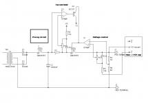
You take a xformer and a bridge, but after the bridge before you go to the reservoir cap, you go through a power fet to charge the caps. After the cap you have the adjustable series regulator.
There are also two comparators: One switches hi if the voltage at the fet drain is above the cap voltage, meaning there is voltage available to charge the cap.
The 2nd comparator switches hi if the voltage difference between the cap and the regulator output voltage falls below let's say 3 volts, meaning the cap has to be refilled.
When both comparators are hi, the fet is switched on. If either of the 2 comparators switches low again, the fet is turned off.
This way, you still have the mains frequency charge cycle, but only enough as required by the output voltage.
Anyway, I will look up my schematics and post what I have, but since I am on the road it will be not before the weekend.
Jan Didden
No, not basically, but I hesitate because it is one of the first things I did and is really ugly. There are better ways to do it today.
I thought about this:
You take a xformer and a bridge, but after the bridge before you go to the reservoir cap, you go through a power fet to charge the caps. After the cap you have the adjustable series regulator.
There are also two comparators: One switches hi if the voltage at the fet drain is above the cap voltage, meaning there is voltage available to charge the cap.
The 2nd comparator switches hi if the voltage difference between the cap and the regulator output voltage falls below let's say 3 volts, meaning the cap has to be refilled.
When both comparators are hi, the fet is switched on. If either of the 2 comparators switches low again, the fet is turned off.
This way, you still have the mains frequency charge cycle, but only enough as required by the output voltage.
Anyway, I will look up my schematics and post what I have, but since I am on the road it will be not before the weekend.
Jan Didden
Great, thanks. I will probably still check what the stepped input voltage might do for me but the FET switching sound nice to.
/UrSv
/UrSv
I think everyone here has convinced me that I need to do some sort of preregulator. I think it shouldn't be to hard to add inrush current limiting also with the same fet. Something like a series resistor to sense current and a comparator to turn off the fet if the current is too high. It would have been nice If I had thought of that before I had the pcb's made, but I provided plenty of connections that are accessible so I should be able to do this with an additional board. I think I will use mosfets or darlingtons between the bridge and the caps, and make the cap voltage about 5-10V more than the output. With that I would be able to do 10A x 2 at any voltage with only 100W of heat. The preregulator devices shouldn't put out much heat so I can mount them on the chassis beside the bridges.
I must be truly addicted to diy since I already have another mouser list starting before my last order gets here.
Darrell Harmon
I must be truly addicted to diy since I already have another mouser list starting before my last order gets here.
Darrell Harmon
Regulated etc
Hi Darrell,
Glad you liked my idea!
Two more pieces of advice: I'm not sure I understand you, but using the fet as an inrush-current limiter may limit your available output power. The principle that at high output voltages and current you only have a fraction of the mains cycle available to charge the cap is still valid. So limiting the current will limit output voltage at high loads. That may or may not be a problem depending on your excess voltage out of the xformer relative to your max required output voltage.
BTW, you cannot use the fet to limit output current because there is still a full cap downstream on which you have no control. So that must be done in the series reg.
Another thing to remember: the series regulator must of course be able to withstand the max output voltage. Suppose you are at 100V output voltage, with a light load. Then you decide to turn the output down to zero volts. Guess what: the cap is still charged to that 100V and will take time to bleed away, so there's 100V across your series regulator. Not necessarily a problem, but keep it in mind.
In my design I have the series regs floating with a +/- 15V supply referenced to the output voltage. In that way, the whole reg including its supplies, moves up and down relative to the supply ground. There are two of these identical supplies, and at the output binding posts the neg terminal of one is connected to the pos terminal of the other to get the midpoint. The output level is set by a dual 3-turn ww precision pot, one for each supply half, these things track at 1% or better.
Jan Didden
Yes, this is the most common way to build regulated PSU's, and is how I intend to build my next ones. The only tricky bit is ensuring extremely accurate tracking, but for most purposes this isn't really necessary.In my design I have the series regs floating with a +/- 15V supply referenced to the output voltage. In that way, the whole reg including its supplies, moves up and down relative to the supply ground
Now, I like that! Simple, and probably not much worse than the electronic solutions. Thanks for that - I'll think carefully about including it...🙂The output level is set by a dual 3-turn ww precision pot, one for each supply half, these things track at 1% or better.
My PSU was rather more complicated - the two regulators are complementary. But, the tracking is extremely accurate - the two voltmeters have 0.01V resolution, and they always agree perfectly when the supply tracks...
An externally hosted image should be here but it was not working when we last tested it.
Inrush current limit with fet:
I don't know what I meant in that post since I have had many ideas. What I am thinking now is something to slow dv/dt of the capacitors to a reasonable level when it is switched on or the voltage is increased fast. I have 80000 uF on each rail, so I = 0.08dv/dt. To keep inrush below 15A rms per rail I would need to keep dv/dt below 187.5V/s. Should be easy with a resistor and a capacitor feeding the comparator rather than a fast input. This is probably very confusing. I am suprised I can charge the caps that fast with that little current. 0.2seconds with only 900W input.
How I dealt with voltage limits of opamps:
I used +- 15V supplies and standard opamps for most everything, and used opamps made out of transistors for the HV. I used 140V rated parts so it can take +-70V rails. TI makes some 100-300V rated opamps that aren't all that expensive, but I chose not to use them.
Meter:
If anyone is interested in the code for my voltmeter I can email it. It is in C for atmel AVR. I used an atmel at90s4433 with a built in 6ch 10 bit adc it has a connection for an external ref. I used a surplus 4x20 character lcd so all 6 voltages are displayed at once. Total cost was less than $20.
Regulated etc
DHARMON,
Trying to limit inrush current means you have to accurately control the conductance of the fet. That will be hard and probably not worth the hassle. Also, that will very much increase the dissipation in the fet, as it is now a resistor rather than a closed switch. (This is of course the reason why inrush current limiting limits the output voltage at high loads and high voltage. The missing power is used to fry the fet! Mother Nature is willing to trade, but doesn't give anything away).
You can avoid all that hassle with hi-voltage opamps by floating the series reg with the output voltage. I will try to post a rudimentary diagram tomorrow. Only drawback is you need separate +/- 15V floating supply.
By the way, you can charge your cap fast, only because you neglected load current. If you draw 850 watts from it, and you have 900watts available, the charging will be much slower. Actually, even 0.2 secs is s l o w compared with load transients you want to catch.
Jan Didden
Re: Regulated etc
I did a bad job explaining what I wanted to do. The preregulator will take an input voltage which is the desired voltage for the caps. The fet will be between the bridge and the caps. The fet will be turned on only when the voltage coming off the bridge is lower than the desired voltage on the caps. The idea is to slowly ramp up input voltage to the preregulator so it will not have to charge the caps so fast.
High voltage opamps don't really bother me. Thats just a personal preference over floating things since I don't want another supply.
janneman said:DHARMON,
Trying to limit inrush current means you have to accurately control the conductance of the fet. That will be hard and probably not worth the hassle. Also, that will very much increase the dissipation in the fet, as it is now a resistor rather than a closed switch. (This is of course the reason why inrush current limiting limits the output voltage at high loads and high voltage. The missing power is used to fry the fet! Mother Nature is willing to trade, but doesn't give anything away).
Jan Didden
I did a bad job explaining what I wanted to do. The preregulator will take an input voltage which is the desired voltage for the caps. The fet will be between the bridge and the caps. The fet will be turned on only when the voltage coming off the bridge is lower than the desired voltage on the caps. The idea is to slowly ramp up input voltage to the preregulator so it will not have to charge the caps so fast.
High voltage opamps don't really bother me. Thats just a personal preference over floating things since I don't want another supply.
I tried out my idea in spice and it actually works.🙂 I will post schematics and waveforms on my website next time I boot Linux. The fet is used as a switch, not a resistor. I simulated loads up to 10A and it did fine. The fet should dissipate minimal power. A high voltage comparator will be needed unless the circuit is modified some. This was mainly just to prove the concept.
Darrell Harmon
Darrell Harmon
Regulated etc
This is how my bench supply looks (except that the prereg is a phase-controlled thyristor thing).
The floating +/-15V supply is a simple PCB-transformer 100mA with a couple of 3-terminal regulators.
Of course, the full schematic has more parts, but this is it conceptually.
Jan Didden
This is how my bench supply looks (except that the prereg is a phase-controlled thyristor thing).
The floating +/-15V supply is a simple PCB-transformer 100mA with a couple of 3-terminal regulators.
Of course, the full schematic has more parts, but this is it conceptually.
Jan Didden
Attachments
Thanks Jan,
Looks somewhat like what I had in mind except that I was looking at the stepped input voltage which is crude but would maybe work fine.
Thanks again,
UrSv
Looks somewhat like what I had in mind except that I was looking at the stepped input voltage which is crude but would maybe work fine.
Thanks again,
UrSv
A Variac Works Fine....
For power amp experimenting, the usual transformer, bridges and caps fed from a variac with a lamp in series with the transformer primary works very well.
If there is any fault, virtually all power is dissipated in the lamp.
I use this variac/lamp setup for servicing all amplifiers, and it saves expensive blowups perfectly.
Eric.
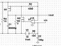
The top wire is rectified ac. The bottom wire is ground. (I'm to lazy to reboot to windows to add labels.) R1 is necessary to pull down the voltage off the bridge so the comparator can sense it. (at least in spice - it wouldn't start up without it.) C1 is of course the main filter cap. M1 is the switch, and M2 is to make it possible to switch with a signal referenced to ground. R5 and C2 are to cause the voltage to ramp up slowly avoiding large current flow on turn on or when the voltage is increased. The comparator turns the fet on whenever the rectifed ac voltage is less than the input. R3 is the load. Rather than attatch waveforms I will offer to email a copy of the file for LTspice. LT spice can be downloaded for free from http://www.linear.com I had to hack some models to make the parts good enough for this. LTspice has no good mosfets, so I just added a 0 to the breakdown voltage of one. It puts out 2V less than the input is set with a 10A load and 80000uF, and with no load it puts out the set voltage.
It seems like combining this with janneman's schematic would result in a good psu. It needs some changes such as possibly putting M2's source at a negative voltage so it would work at low voltage settings. It also needs some zeners and resistors of something like that to not blow the gates out of the fets. One other thought would be a gate driver or an optoisolator rather than the second fet. I know I have seen optoisolated gate drivers (a lot of photodiodes in series). I may just use a darlington PNP in my design rather than the fet because things would be simpler.
This is a very rough version of what I want to do. I will probably test some hardware this weekend since I don't trust spice too well.
Darrell Harmon
Attachments
dlharmon said:[snip]
The comparator turns the fet on whenever the rectifed ac voltage is less than the input. (1)
[snip]
It needs some changes such as possibly putting M2's source at a negative voltage so it would work at low voltage settings (2)
[snip]
Darrell Harmon
Darrell,
(1) is a good idea. I had this synchronised to the mains, but your method will work well. the next thing of course is when to switch the fet OFF , when the cap voltage is well above the output voltage, taking into account that the cap must be able to provide the output current until next charge cycle. you can be quite creative here.
(2) you start to discover the reasons why I went to a floating supply...
Jan Didden
janneman said:
Darrell,
(1) is a good idea. I had this synchronised to the mains, but your method will work well. the next thing of course is when to switch the fet OFF , when the cap voltage is well above the output voltage, taking into account that the cap must be able to provide the output current until next charge cycle. you can be quite creative here.
(2) you start to discover the reasons why I went to a floating supply...
Jan Didden
1. I am planning to use an opamp to add about 5V to the desired regulated output voltage for the input to the prereg. (ripple at 10A was about 2 volts).
2. Yes a floating supply is a great way to do it, but I already have a huge 48VCT transformer and want to have dual supplies using it. It will be semi complex but it should work. It also has some other windings that I can use to provide floating supplies if necessary.
Darrell Harmon
consider a doubler
I know that you will need big HV/High current caps, but I am doing this with a supply right now.
I took the ripple calculations from an old ARRL handbook to find the values -- they used doublers and triplers in some of the KW amplifiers back in the 1960's -- if you have a CAD program it isn't hard to do.
- Status
- Not open for further replies.
- Home
- Design & Build
- Parts
- Regulated bench PSU