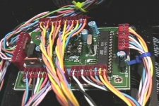
The positive output board. I cheated and used OPA445's (90V supply opamp) since some happened to get sent to me. Someone I was doing some work for sent me 9 with no idea I was working on this. They are great. It is a voltage follower with 3x IRFP240.
Darrell Harmon
Darrell Harmon
Attachments
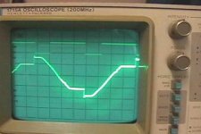
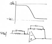
Top trace is mosfet gate. 10V / div. The source is connected to the caps which were at 20V during this test. Output current was about 2A. It was running with a 200W series bulb on the AC. The other trace is the AC off the transformer at 20V /div. That's all for now. I need to draw some schematics.
Darrell Harmon
Darrell Harmon
Attachments
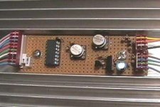
regulated etc
Hi Darrell,
Seems you did a good job here. Did you already post the preregulator schematic? (Didn't find it yet). I would be interested in that.
Jan Didden
Hi Darrell,
Seems you did a good job here. Did you already post the preregulator schematic? (Didn't find it yet). I would be interested in that.
Jan Didden
I have been really busy lately. I should be able to do that in about 2 weeks. I have not drawn it on the computer yet. I just have some really bad hand drawn ones that no one would understand.
Darrell Harmon
Darrell Harmon
Found a link
I am just a new learner in electronics. I bought a regulated dc power supply with variable voltage from 5 to 24V 6A. When I tried matching mosfets for Aleph 2, I found that the power supply is not stable enough thus giving me different result everytime I measure the Vgs on the mosfet. I checked the internet and found http://www.uoguelph.ca/~antoon/circ/circuits.htm
and I am interested in building his power supply design with perhaps a digital readout instead of analog. Hope this can also give you some idea. Cheers.
Hi Kristian,
First, your power supply may not be at fault. As FETS change temperature, the Vgs will change as well. This can cause one to think that something is wrong when you re-measure a FET. The temperature may be vastly different.
Best Regards,
Dale
By the way, any sign of your boards yet?
First, your power supply may not be at fault. As FETS change temperature, the Vgs will change as well. This can cause one to think that something is wrong when you re-measure a FET. The temperature may be vastly different.
Best Regards,
Dale
By the way, any sign of your boards yet?
Power Supply
Hi Dale,
I think the temperature is not the problem here . Well, from what I observed is the voltage that this coming out from the output jack from my DC ps will vary and it affect the Vgs value that I measure. For example, I set the ps at 15V and start matching let say 1st mosfet is 4.10 V and when I check it again it read 4.02V and the DC coming out from the ps has dropped by a couple of Volts. Anyway, I paid onlylike US$3 for the ps and I had my expectation too much out of it, there is no such thing as a free lunch I guess.
PS. I think it will take several weeks for the boards to arrive if you sent it by postal mail. As a matter of fact, I tried not to think about it too much (it hurts so much to wait for such an eternity, lol).
Hi Dale,
I think the temperature is not the problem here
. Well, from what I observed is the voltage that this coming out from the output jack from my DC ps will vary and it affect the Vgs value that I measure. For example, I set the ps at 15V and start matching let say 1st mosfet is 4.10 V and when I check it again it read 4.02V and the DC coming out from the ps has dropped by a couple of Volts. Anyway, I paid onlylike US$3 for the ps and I had my expectation too much out of it, there is no such thing as a free lunch I guess. PS. I think it will take several weeks for the boards to arrive if you sent it by postal mail. As a matter of fact, I tried not to think about it too much (it hurts so much to wait for such an eternity, lol).
Pre-regulator design
I Have been following this thread with some interest for a while.
My last attempt at serious PSU building resulted in half a dozen melted MJE2955 Pass transistors (particularly worrying when their failiure mode results in shorting Emitter and Collector, putting unregulated supply straight to output!).
As a result i'm extremely interested in seeing some completed schematics, specifically for the pre-regulator circuit discussed through this thread:
A final note:
Just out of interest to other PSU builders out there - how accurate have you found current limiting designs, such as those shown above in this thread - have you found your design resilient to oscillation or overshoots in output voltage? A previous, soon abandonned PSU could oscillate between 0 and 10v, sinking up to 10A whilst "current limiting".. at 200 Khz ..
Probably would have made a good LW radio transmitter!
I Have been following this thread with some interest for a while.
My last attempt at serious PSU building resulted in half a dozen melted MJE2955 Pass transistors (particularly worrying when their failiure mode results in shorting Emitter and Collector, putting unregulated supply straight to output!).
As a result i'm extremely interested in seeing some completed schematics, specifically for the pre-regulator circuit discussed through this thread:
It would be great to see the schematic for a successful design; 300W of power dissipation caused previous supply failure and smoking of power transistors!I have been really busy lately. I should be able to do that in about 2 weeks. I have not drawn it on the computer yet. I just have some really bad hand drawn ones that no one would understand.
Darrell Harmon
A final note:
Just out of interest to other PSU builders out there - how accurate have you found current limiting designs, such as those shown above in this thread - have you found your design resilient to oscillation or overshoots in output voltage? A previous, soon abandonned PSU could oscillate between 0 and 10v, sinking up to 10A whilst "current limiting".. at 200 Khz ..
Probably would have made a good LW radio transmitter!
I have spring break next week so I should get something drawn. The current limit doesn't work all that well, but I finally got it to where it just latches to 0V if there is overcurrent which is just as good for my purposes (keeping the magic smoke in parts). I put 1000uF caps on the output to help keep the output clean with nasty loads like switching power supplies, and this is why current limit refused to do anything but oscillate. (It saw the caps as a near short circuit when it tried to bring the voltage back up) The actual voltage regulator could use some improvements, but the prereg is perfect.
I am using burr brown OPA445's, and these really like to oscillate if used wrong. It got over 100 MHz once. I didn't know 3x parallel IRFP240's could be that fast . Getting a scope probe anywhere near it would show a trace!!! 2 different grounds had several volts of RF between them. One other interesting note is that one Zen i built was oscillating at about 1MHz and I could actually tune in the music on AM radio. If I turned the amp on I heard my music, and if I turned it off I heard preaching. A bypass cap on the power supply solved that one. The wires were too long coming from the caps.
I haven't gotten anything done with my website lately since school has been keeping me too busy. Hopefully that will change next week. One other little thing I am planning to add to the power supply is sort of like soft start: gradually increase the voltage setting of the preregulator at power up to avoid big inrush currents. I repaired a flash a few weeks ago that charged 8000uF to 450V (approx 600J) in 2 seconds from a tripler connected to the ac line. It used this same priciple (using triacs instead of mosfets).
Darrell Harmon
I am using burr brown OPA445's, and these really like to oscillate if used wrong. It got over 100 MHz once. I didn't know 3x parallel IRFP240's could be that fast
. Getting a scope probe anywhere near it would show a trace!!! 2 different grounds had several volts of RF between them. One other interesting note is that one Zen i built was oscillating at about 1MHz and I could actually tune in the music on AM radio. If I turned the amp on I heard my music, and if I turned it off I heard preaching. A bypass cap on the power supply solved that one. The wires were too long coming from the caps.I haven't gotten anything done with my website lately since school has been keeping me too busy. Hopefully that will change next week. One other little thing I am planning to add to the power supply is sort of like soft start: gradually increase the voltage setting of the preregulator at power up to avoid big inrush currents. I repaired a flash a few weeks ago that charged 8000uF to 450V (approx 600J) in 2 seconds from a tripler connected to the ac line. It used this same priciple (using triacs instead of mosfets).
Darrell Harmon
Thanks, I have been trying similar things, but haven't had the right capacitor values. I will get some more caps and try again. The voltage section is working fine. All I need to do is get the current limit to work right and it will be finished. I also think my grounding could be improved.
Darrell Harmon
Darrell Harmon
DHarmon - look at this PPT link
If you have fast internet access you should download this PowerPoint presentation by ON Semi -- I think the URL is Arizona State University (and Motorola is hq'd there.) It goes into the math:
<url>http://www.ceaspub.eas.asu.edu/eee488a/EEE 489 (ON).ppt</url>
If you have fast internet access you should download this PowerPoint presentation by ON Semi -- I think the URL is Arizona State University (and Motorola is hq'd there.) It goes into the math:
<url>http://www.ceaspub.eas.asu.edu/eee488a/EEE 489 (ON).ppt</url>
I downloaded it, but the equations were scrambled and mostly ?'s because I was using Openoffice instead of M$ Office. Maybe I will try on someone else's computer. I will see what I can find at the library too. Art of Electronics probably has some information. Guessing at cap values is not much fun.
Darrell Harmon
Darrell Harmon
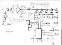
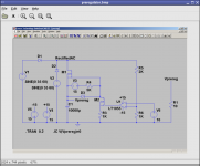
Here is the preregulator schematic. It works reasonably well. I can email you the SwitcherCad file if you like. You can download the program from http://www.linear.com
I should be able to do better with the screenshot, but there was a limit on size that caused some problems I don't have any software on this pc to crop it.
The output will be about 3x V6. M1 is the fet doing the heavy switching. V3 and R4 are just pulling its gate up. V3 is a 15V supply riding on top of the capacitor voltage. It is used for other things in the regulator also. D3 is a 10V zener to protect the gate on M1. M2 and R3 are a current sink that pulls down the gate voltage on M1. U1 is the comparator. You should use a comparator and not an LT1055. I just used that for simulation purposes. It compares the rectified ac divided by 3 with the input voltage, and if the input voltage is greater turns on the switch.
Darrell Harmon
Attachments
Thanks for the schematics - very helpful.
I've attached the schematic of the design I used a while back - it's originally from the national semiconductor LM317 datasheet, reproduced in The Art of Electronics - well if it's in THE book, it must be good 🙂
I added a few more pass transistors, and connected the voltage control resistor via a small regulated negative supply, so the output could go down to 0v.
It worked reasonably (apart from current limiting - unfortunately the main point I chose this design), but has been gathering dust for a while since I had access to some new Thurlby-Thandar power supplies. I've now decided to rebuild it as a different design with pre-regulator.
As for the magic smoke:
The end result: On connection of a low resistance load, one-by-one the transistors reached secondary breakdown, shorted, then blew their bonding wires like fuses!
I've attached the schematic of the design I used a while back - it's originally from the national semiconductor LM317 datasheet, reproduced in The Art of Electronics - well if it's in THE book, it must be good 🙂
I added a few more pass transistors, and connected the voltage control resistor via a small regulated negative supply, so the output could go down to 0v.
It worked reasonably (apart from current limiting - unfortunately the main point I chose this design), but has been gathering dust for a while since I had access to some new Thurlby-Thandar power supplies. I've now decided to rebuild it as a different design with pre-regulator.
As for the magic smoke:
Yes - They were quite happy, connected to each transistor. The problem was I mixed out my pinouts and had wired them to the transistor collectors rather than emittersdid you remember to put the 0.1 ohm resistors in
The end result: On connection of a low resistance load, one-by-one the transistors reached secondary breakdown, shorted, then blew their bonding wires like fuses!
Attachments
dharmon
there are a lot of problems with that design -- doesn't you cad program have a bode plotter?
there are a lot of problems with that design -- doesn't you cad program have a bode plotter?
Re: dharmon
The part I posted works fine in both simulation and reality. The fet runs cold on a tiny heatsink shared with the bridges. I have not yet been able to make the preregulator act bad. Any suggestions for improvement? Btw that opamp should be a comparator. The switching fet sees a nice 10V square wave from gate to source. (As seen in the picture of the scope screen I posted a while back.)
I am still just learning and only have a few years experience, so a good bit of what I do can be trial and error particularly with compensation and such.
Darrell Harmon
jackinnj said:there are a lot of problems with that design -- doesn't you cad program have a bode plotter?
The part I posted works fine in both simulation and reality. The fet runs cold on a tiny heatsink shared with the bridges. I have not yet been able to make the preregulator act bad. Any suggestions for improvement? Btw that opamp should be a comparator. The switching fet sees a nice 10V square wave from gate to source. (As seen in the picture of the scope screen I posted a while back.)
I am still just learning and only have a few years experience, so a good bit of what I do can be trial and error particularly with compensation and such.
Darrell Harmon
Re power supply
Dear UrSv,
if you are still looking for a power supply with current limit, let me say that the best IC ever made, in my opinion, was MC1466/MC1566 Motorola. It is an old IC and I think could be possible to find even to-day. Since it needs a separate supply (25V few mA), you can control voltages from 0 to how much the series transistors can sustain and with current as you want. You can design supplies, for instance, for 0-15 V-10A or 0-40V-5A or 0-250V-250mA or as your need. It exhibits excellent line voltage, load voltage and current regulation. One of the most important points, for me, is the current limit knee: it is very sharp. If you use 723, when you reach the current limit, the voltage goes down strongly. This doesn't happen with MC1466/1566. If you are unable to find its data-sheet, let me know. I'll send it to you.
Milo
- Status
- Not open for further replies.
- Home
- Design & Build
- Parts
- Regulated bench PSU