Mooly, I changed a few things that you started with.
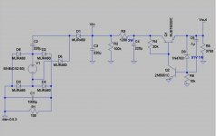
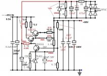
R3 in addition to reducing ripple lowers the dissipation in Q1 to about 870mW.
Transistor models are Bob Cordel's.
Better yet leave R2 out, you get an extra 2db ripple rejection.
R3 in addition to reducing ripple lowers the dissipation in Q1 to about 870mW.
Transistor models are Bob Cordel's.
Better yet leave R2 out, you get an extra 2db ripple rejection.
Attachments
Last edited:
Hi RJM1,
That looks good in implementing and spreading the dissipation and using a better regulator. I'll have a closer look later 🙂
These simple circuits and ideas can be refined and elaborated on greatly.
That looks good in implementing and spreading the dissipation and using a better regulator. I'll have a closer look later 🙂
These simple circuits and ideas can be refined and elaborated on greatly.
I'll have a closer look later 🙂
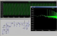
The performance seems pretty good.
Only comment would be the potential of a low impedance path into the B-E junction... makes me twitchy seeing that 🙂
For me it seems, that this is the solution for the regulated 81V supply .... Am I right?
What's the Pro's and Con's of the Voltage Doublifier?
What's the Pro's and Con's of the Voltage Doublifier?
A doublifier 🙂
Pro's... there is no other transformer involved which to me is a big bonus. Less chance of mechanical and radiated hum/noise. Its simple, or at least as simple as you want it to be. The regulator is as complex whatever happens to feed it and not really part of the doubler as such.
Cons... it doubles so there is unwanted voltage to "lose" in the regulator. That means heat generation. For the low currents involved its not a big issue though. The caps need to be good quality, again not an issue.
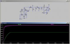
Heres a quick lash up of a different regulator. This can adjustable by varying R5. As before ignore transistor types.
Pro's... there is no other transformer involved which to me is a big bonus. Less chance of mechanical and radiated hum/noise. Its simple, or at least as simple as you want it to be. The regulator is as complex whatever happens to feed it and not really part of the doubler as such.
Cons... it doubles so there is unwanted voltage to "lose" in the regulator. That means heat generation. For the low currents involved its not a big issue though. The caps need to be good quality, again not an issue.
Heres a quick lash up of a different regulator. This can adjustable by varying R5. As before ignore transistor types.
Attachments
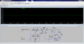

I'll post a pic when all the components are on ....
Maybe also some diagrams about the voltage ... If possible.
Maybe also some diagrams about the voltage ... If possible.
Ingo, do you have a scope?
A friend of mine has one ...... tomorrow we'll start to solder and maybe take some measurements ....
Not sure whether we can copy or print them ....
Gentlemen,
For my Project I Need a 80v regulated Supply. I have a double rail +80V/0V PSU.
I'm only a mechanical engineer and Need a prinicipal Sketch how it Looks like ...
See also here: http://www.diyaudio.com/forums/solid-state/214899-diy-project-nytech-cpa602-today-3.html#post3096379
Thanks for your help ...
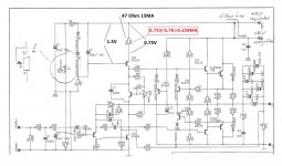
Here's a circuit diagram for you , and out put battery sound. But your amplifier's circuit diagram is not correct.
Attachments
Last edited:
peizi...
Why are you posting the same image in all your posts ?
Your contributions are most welcome but please explain any relevance to circuits posted.

Why are you posting the same image in all your posts ?
Your contributions are most welcome but please explain any relevance to circuits posted.
Same image ? no , That's replied NRWler04 the same question. I have posted one post in this forum that's my first post.(DIY Cambrige DAC Magic)peizi...
Why are you posting the same image in all your posts ?
Your contributions are most welcome but please explain any relevance to circuits posted.
NRWler04 is not an electronics engineer, He don't understand any professional explain.
Last edited:
Same image ? no , [/B]
Yes 🙂
This one
http://www.diyaudio.com/forums/digital-line-level/217585-diy-cambrige-dac-magic.html#post3119391
Again an update from the non electronics engineer 
So, we assembled the PSU ....
Beside it looks good, it seems, that there is also a good stable supply of ~75V. As already expected, also the 75V regulated shows only something about 73V. I used two 30V and one 15V Zener Diodes.
Here are some pics:


Sorry for the poor quality, it's an iPhone ....
And the new PSU fits also in the original NYTECH CPA 602 box ...
As you can see here:

Now I need a beer ... Or maybe two .....
So, we assembled the PSU ....
Beside it looks good, it seems, that there is also a good stable supply of ~75V. As already expected, also the 75V regulated shows only something about 73V. I used two 30V and one 15V Zener Diodes.
Here are some pics:
Sorry for the poor quality, it's an iPhone ....
And the new PSU fits also in the original NYTECH CPA 602 box ...
As you can see here:
Now I need a beer ... Or maybe two .....
Cheers! But isn't it a Zener circuit with no extra secondary? How can you expect to get a higher voltage? And why do get only 75V? What are the specs of the transformer?
That out put voltage are difference.
Peizi ...
what is wrong in my Amp ..... ??????
see your circuit diagram and I modified it here
Attachments
- Status
- Not open for further replies.
- Home
- Amplifiers
- Power Supplies
- Regulated +80V Supply ....