So I see thre options:
1.) Use a Toroid with 60 - 65V AC .... will gif ~ 90V DC ....
- Regulate down to 80V for the VAS
- What will happen to the rest ....? Burning?
2.) Regulate Supply down to 75V ....
- Some changes in the resistors in the VAS neccessary?
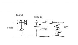
3.) Using a Voltage Doubler ....
- How stable is it?
- Can you make a small sketch again?😉
What about the proposal from lohk ....?
Today afternoon maybe I can prepare the schematics, latest tomorrow morning.
Regards from Germany (TGIF)
Ingo
1.) Use a Toroid with 60 - 65V AC .... will gif ~ 90V DC ....
- Regulate down to 80V for the VAS
- What will happen to the rest ....? Burning?
2.) Regulate Supply down to 75V ....
- Some changes in the resistors in the VAS neccessary?
3.) Using a Voltage Doubler ....
- How stable is it?
- Can you make a small sketch again?😉
What about the proposal from lohk ....?
Today afternoon maybe I can prepare the schematics, latest tomorrow morning.
Regards from Germany (TGIF)
Ingo
🙂
1. Probably not the best option.
2. Could be very good. There should be minimal work needed. Just set the output midpoint (with no load) so that clipping is equal.
3. Very stable as there is a large differential. The caps are a little trial and error as much depends on the current required.
1. Probably not the best option.
2. Could be very good. There should be minimal work needed. Just set the output midpoint (with no load) so that clipping is equal.
3. Very stable as there is a large differential. The caps are a little trial and error as much depends on the current required.
Attachments
.... hopefully it will not burn😀🙄😱
There is a 4th option:
- Setup a small piggyback transformer on top of the existing torroid with it's own low power rectifier and smooting cap with a small transistor regulator ...
There is a 4th option:
- Setup a small piggyback transformer on top of the existing torroid with it's own low power rectifier and smooting cap with a small transistor regulator ...
What is the value of R13 ? On the circuit it looks like 47K which can't be correct. I would have guessed at something around 82 ohm
What is the value of R13 ? On the circuit it looks like 47K which can't be correct. I would have guessed at something around 82 ohm
Original schematics says R213 = 47 .....
.... hopefully it will not burn😀🙄😱
There is a 4th option:
- Setup a small piggyback transformer on top of the existing torroid with it's own low power rectifier and smooting cap with a small transistor regulator ...
Hmmm... workable but a bit messy maybe. More chance of mechanical and induced hum too.
It wouldn't my choice tbh
I would not use a voltage doubler for the supply of the VAS/inputstage. Do not ask for the reason...
I was proposing a super simple solution like this:
80V+--from-psu-----supply-powerstage-----diode->---100R---47yF/100V_to_ground---supply-VAS/first_stage
I think the "decoupling" should be sufficient and the slight voltage loss is of no concern.
I was proposing a super simple solution like this:
80V+--from-psu-----supply-powerstage-----diode->---100R---47yF/100V_to_ground---supply-VAS/first_stage
I think the "decoupling" should be sufficient and the slight voltage loss is of no concern.
I would not use a voltage doubler for the supply of the VAS/inputstage. Do not ask for the reason...
I was proposing a super simple solution like this:
80V+--from-psu-----supply-powerstage-----diode->---100R---47yF/100V_to_ground---supply-VAS/first_stage
I think the "decoupling" should be sufficient and the slight voltage loss is of no concern.
I'll try to setup a schematic tomorrow morning directly and post it ....
Ingo

47 ohm sounds more reasonable. That would give around 14ma VAS current.
Changed 😱
Changed 😱
🙂 Never take circuit diagrams at face value although mostly they are pretty good.
The above diagram looks OK. It achieves "isolation" rather than regulation and so the voltage will still rise and fall as it follows the main rails but with a larger time constant.
The above diagram looks OK. It achieves "isolation" rather than regulation and so the voltage will still rise and fall as it follows the main rails but with a larger time constant.
😕
This means? It's an easy good solution?
I thought about the 70V regulation ..... I have the PCB-Layout ready.
Last edited:
It could work very successfully with no regulation at all. Adding 70v regulation might be better but as ever it's hard to say without listening tests.
You have to trust your own judgement and stand by what sounds good to you.
You could always add the second stage of regulation to the bias network because that is probably the most sensitive with regard to noise/hash etc. The amp (VAS stage) is probably fairly imune to injection of noise from the positive PSU rail.
Here's an update for the PSU Layout. So far only with 70V regulation .....
http://www.pinkfishmedia.net/forum/showpost.php?p=1749979&postcount=36
http://www.pinkfishmedia.net/forum/showpost.php?p=1749979&postcount=36
- Status
- Not open for further replies.
- Home
- Amplifiers
- Power Supplies
- Regulated +80V Supply ....