Good luck with it all, the PCB's are looking good up to now. Listening tests are probably the next step.
Mooly, I'll keep you updated .... PCB's will go into Production on Wednesday.
Regards from Germany
Regards from Germany
Mooly, I'll keep you updated .... PCB's will go into Production on Wednesday.
Regards from Germany
Done ....🙄
To continue the discussion: How would a Mini-PSU for 24mA 90 look like? Has anybody an idea for the Tranny and the components?
Many options. An 80v (40-0-40) tranny will give around 115 volts dc when rectified.
If the 24ma were a known constant load then a simple zener stabiliser as mentioned earlier would be OK. If the load were variable and with the possibility of there being no load then a simple linear regulator might be better (more efficient and cooler running.
That could be a simple or complex as you wished. A zener reference and emitter follower would suffice with series low value resistor to limit surge currents.
This are the big Trannys I use in my CPA 602 .....
I think, the trafo need's 4VA as it should supply only the VAS ...... The problem is, I have only 20mm height available. The small VAS-PSU should sit on the big Toroid. This is the fourth option out of our discussion from the beginning.
The new PSU is no in production with the Zener Regulation.
I think, the trafo need's 4VA as it should supply only the VAS ...... The problem is, I have only 20mm height available. The small VAS-PSU should sit on the big Toroid. This is the fourth option out of our discussion from the beginning.
The new PSU is no in production with the Zener Regulation.
.... hopefully it will not burn😀🙄😱
There is a 4th option:
- Setup a small piggyback transformer on top of the existing torroid with it's own low power rectifier and smooting cap with a small transistor regulator ...
You mean this option...
So what is it you need to know 🙂
So what is it you need to know 🙂
Well, I think I know now the principal of the PSU. Do we regulate with a zener or with a voltage regulator ....
The main question is, how we generate the 90 - 95V out of a small Toroid which sits on the top of the big ones.
Until now I did not find a Toroid with 20 mm height which give me 90 V .....
The target is still, to generate a very stable 81V supply for the VAS .....
You need a zener type reference whatever method is chosen.
The shunt regulator in post #6 is good if the load is fairly constant because the values can all be scaled to give an efficient design.
If the load varies then a regulator is best such as a one transistor + zener type.
If you can't find a toroid that physically fits then you have to look at other options such as the voltage doubler. I think that would be my choice anyway as multiple transformers always seem a bit messy.
This one will fit perfectly ......
It has 5VA will provide 2 x 22V. How we get the voltage to the level we need .....
http://docs-europe.electrocomponents.com/webdocs/0030/0900766b80030e2f.pdf
It has 5VA will provide 2 x 22V. How we get the voltage to the level we need .....
http://docs-europe.electrocomponents.com/webdocs/0030/0900766b80030e2f.pdf
This one will fit perfectly ......
It has 5VA will provide 2 x 22V. How we get the voltage to the level we need .....
http://docs-europe.electrocomponents.com/webdocs/0030/0900766b80030e2f.pdf
Messy... you would need multiple voltage doublers cascaded to increase the voltage.
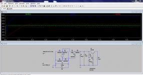
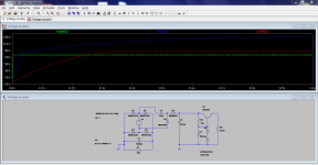
Look at this.
Green is main 82 volt rail
Blue is doubler output
Red is regulated.
Ignore the actual semiconductor types... they were standard models.
R4 is your 24ma load.
V1 is the main transformer.
This looks really good ..... I'll do this for my Mono-Blocks .....
For the existing 602's I'll go with the regulated 70V-75V Solution ....
I'll setup the schematic for the PSU and will prepare an experimental PCB.
What will happen under high load? Will the Voltage brake down or is there allway enough room/flexibility?
Look at this.
Green is main 82 volt rail
Blue is doubler output
Red is regulated.
Ignore the actual semiconductor types... they were standard models.
R4 is your 24ma load.
V1 is the main transformer.
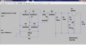
I'm very confused with your circuit...D1 to D4 (the bridge), what are they contributing to your voltage doubler ?
Also with two 8V2 zeners at the base of TR1, surely Vb = 16v4 and thus Ve will be about 0.7V below that = 15.7V ish.
I know that you said to ignore the actual semiconductor types, I assume D8 and D7 zener voltages would add up to 90V, but Q1 will have to be bigger than a 2n5500 as it will dissipate 60V*.024A= 1.44W. You might want to increase the value of R2 to 100K because at 1000 ohms it will dissipate 22W.
Last edited:
I'm very confused with your circuit...D1 to D4 (the bridge), what are they contributing to your voltage doubler ?
Also with two 8V2 zeners at the base of TR1, surely Vb = 16v4 and thus Ve will be about 0.7V below that = 15.7V ish.
Thats right, D1 to D4 contribute nothing to the doubler or reg.
I put them in to make sure the circuit worked as a whole when the two grounds were joined. Just wanted to prove to myself it was OK
The zeners are an 82v and 8.2 ? was it. I just used the available models and these added up to around 90 volts.
I know that you said to ignore the actual semiconductor types, I assume D8 and D7 zener voltages would add up to 90V, but Q1 will have to be bigger than a 2n5500 as it will dissipate 60V*.024A= 1.44W. You might want to increase the value of R2 to 100K because at 1000 ohms it will dissipate 22W.
Zeners as you say and the transistor.... well in LTspice they don't smoke or burn a hole in the screen. A scan of the catalogues will show suitable devices.
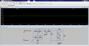
R2... I honestly hadn't noticed I left it at 1 K. It was there from when I was building up the doubler from scratch and before I added the reg so I'll re-run the sim. Well spotted... thanks
Here's a re-run with no R2 and also a test of how much current it can deliver. Note the increase in the value of the caps to get more current.
As to the regulator, well this is as simple (but still good) as it gets. You could design a more elaborate regulator with error correction which would be a two or three transistor circuit. You could also add series R/C/R/C filtering before the reg. That could also usefully be used to spread the total power dissipation. It all depends on how complex you want it all to be.
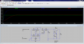
Remember the series pass transistor will get hot at high currents and needs to be rated accordingly. 160 volts in and 90 volts out at 24ma means around 1.7 watts transistor dissipation. If the load is known and reasonably constant then the caps can be sized to reduce the 160 volts down a little by using the reactance of the cap to "drop" the voltage with no power loss.
Look at the component values and voltage scale to see the differences in these examples...
As to the regulator, well this is as simple (but still good) as it gets. You could design a more elaborate regulator with error correction which would be a two or three transistor circuit. You could also add series R/C/R/C filtering before the reg. That could also usefully be used to spread the total power dissipation. It all depends on how complex you want it all to be.
Remember the series pass transistor will get hot at high currents and needs to be rated accordingly. 160 volts in and 90 volts out at 24ma means around 1.7 watts transistor dissipation. If the load is known and reasonably constant then the caps can be sized to reduce the 160 volts down a little by using the reactance of the cap to "drop" the voltage with no power loss.
Look at the component values and voltage scale to see the differences in these examples...
Attachments
- Status
- Not open for further replies.
- Home
- Amplifiers
- Power Supplies
- Regulated +80V Supply ....