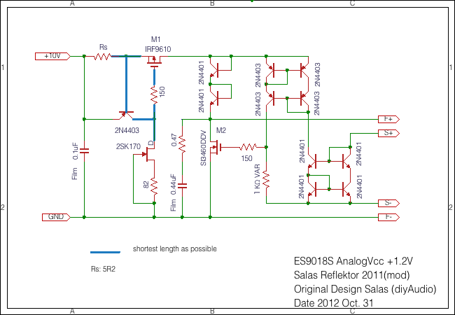
For +/-12Vdc output you need 15+15Vac (four wire) transformer either for stacked 2x Ref-d with mod in Vref or for +/- sections Bib (just on its trimmer)
In the early days of the Reflektor there where a shematic for a 1,2v version but when searching for it today all I can find is that it's not recomended for that region.
Was this a bad idea ? If not, how would you easiest do this on the existing pcb?

Was this a bad idea ? If not, how would you easiest do this on the existing pcb?

Its not a bad idea, just more complex. Its one of Kazuo's various experiments in Reflektor for everything. He reported it worked but I can't say more from own experience. It can't be done on the normal Ref-d pcb. Those are protoboard making specialized things. Maybe with adding a small daughter board and some vias hacking.
i can't find 15+15 v which isn't toroid in mouser. i'm not a fan of toroid.
are 2 of these (each for ref-d and BiB) will do ?
http://www.mouser.co.id/ProductDeta...g/229D30/?qs=sGAEpiMZZMuFYi0ZsYM5P5YiJtT4S2/v
are 2 of these (each for ref-d and BiB) will do ?
http://www.mouser.co.id/ProductDeta...g/229D30/?qs=sGAEpiMZZMuFYi0ZsYM5P5YiJtT4S2/v
Its not a bad idea, just more complex. Its one of Kazuo's various experiments in Reflektor for everything. He reported it worked but I can't say more from own experience. It can't be done on the normal Ref-d pcb. Those are protoboard making specialized things. Maybe with adding a small daughter board and some vias hacking.
Or an all together new 1.2v salas regulator 😉
I have a bunch of reflektors and Bib's aimed at the new Acko9038 dac (eight regulators in total), maybe I will just go for the akd75 regulator for 1.2v then (x3).
Thanks anyway 🙂
almost forgot. i also need 3.3 v @ 300 mA for logic and usb receiver.
which transformer secondary is correct ? 8 or 6.3 vac ?
which transformer secondary is correct ? 8 or 6.3 vac ?
Hi, if I am using ref-D mini's to power +/-5V for the analog part of DAC, do I need to have J2 with close or same IDSS? Thanks
Close within 1mA idss would be nice so the Yfs characteristics are alike, but true matching is not necessary.Hi, if I am using ref-D mini's to power +/-5V for the analog part of DAC, do I need to have J2 with close or same IDSS? Thanks
If you got build pictures would be nice to see by the way. We have no Mini's builders pics in the thread I think.
Close within 1mA idss would be nice so the Yfs characteristics are alike, but true matching is not necessary.
If you got build pictures would be nice to see by the way. We have no Mini's builders pics in the thread I think.
Hi, Salas,
Thanks. I will post some photos when the board is populated. Need to find out the IDSS of my SK117GR's first. Cheers.
WYAN
Hello Salas,
It seems that the 2SK117GR is obsolete. What can I used instead for the J1 and J2?
Thank you !
It seems that the 2SK117GR is obsolete. What can I used instead for the J1 and J2?
Thank you !
2SK880GR
There are SMT pads for J1 in the REF-D and for J1 & J2 in the REF-D MINI
There are also mini boards converters from SMT to through hole on Ebay etc
There are SMT pads for J1 in the REF-D and for J1 & J2 in the REF-D MINI
There are also mini boards converters from SMT to through hole on Ebay etc
2SK880GR
There are SMT pads for J1 in the REF-D and for J1 & J2 in the REF-D MINI
There are also mini boards converters from SMT to through hole on Ebay etc
Thank you for your answer Salas, I just ordered parts for two boards: 5,5V and 8V.
Because it is a school project I must do the PCB myself, so I want to make all the improvements possible - and I have 2 questions:
1)when using the J2 mode, it is enough to connect G to S or I could use an RR resistor like on the J1 based on the IDSS ?
2) in this thread I found that using a 1,5mH choke before the 10000uF cap improved the filtering. Should I also put a 3300uF cap before the choke to make a CLC filter or this is a overkill ? Or both are overkills ? 🙂
Thank you !
1) Its enough when with between 2-4mA Idss parts
2) Filtering is good extra in general but simulate in Duncan PSU free software before to be smooth rising edge and acceptable voltage loss
2) Filtering is good extra in general but simulate in Duncan PSU free software before to be smooth rising edge and acceptable voltage loss
1) Its enough when with between 2-4mA Idss parts
Do you mean to look after a J2 that has IDSS 2-4mA or that the difference between J1 IDSS and J2 IDSS should be 2-4mA?
Sorry for bothering with so many questions, but:
1) Can I a use a more powerfull N MOS with less Rds on like RFP70N06?
2) Can I use a more powefull P MOS with less Rds on like FQP27P06?
Thank you !
1) Can I a use a more powerfull N MOS with less Rds on like RFP70N06?
2) Can I use a more powefull P MOS with less Rds on like FQP27P06?
Thank you !
- Home
- Amplifiers
- Power Supplies
- Reflektor-D builds