Dear Experts,
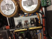
I'm seeing oscillation at around 5.8M powering <20ma/3.3v 49M clock and buffer unit with 10cm length of sense and power cable, CCS runs at 260ma.
Without sense line directly 2 wires, or with 0.5ohm in serial after power/sense feed, there is no oscillation.
Tried to adjust the snubber cap and resistor with not much improvement, hopefully can get some idea here as where to troubleshoot.
Regards
Last edited:
Just revert in two wire short run mode with thicker cabling. Its legit where four wire is kicking back. Not all situations are lending themselves to an exposed sense loop.
Just revert in two wire short run mode with thicker cabling. Its legit where four wire is kicking back. Not all situations are lending themselves to an exposed sense loop.
Thanks Salas!
I wondered if people could comment on the use of local decoupling capacitors in addition to the Reflektor supply. I am in the process of building a PCM1794 DAC and I was going to use the Reflector-D for all supplies. In the PCM 1794 Data Sheet there is local decoupling and I am fully aware that at the MHz frequency that DACs operate, the impedance of the supply is governed by the local decoupling caps. So my question: for a DAC design, should I remove all local decoupling and feed only with the Ref-D, or should I include (indeed is it preferable), for say a 0.1uF/100pF combo close the supply pins?
Start without the local and use two wire mode with the reg in closest proximity to the chip possible, then add the local and compare. Logically the decoupling needs be there. But no harm to test.
in my pcm1794 dddac, I don't have my reflektor-d supplies yet, but I have recently changed from a 0.1uf through hole film cap approx 8mm away from the dac chip to 0.1uf c0g smd caps almost right at the pins and I noticed an improvement in clarity of sound, so I would try test with and without as Salas says, but I suspect they will give you an improvement, just try and get them as close as possible for best results.I wondered if people could comment on the use of local decoupling capacitors in addition to the Reflektor supply. I am in the process of building a PCM1794 DAC and I was going to use the Reflector-D for all supplies. In the PCM 1794 Data Sheet there is local decoupling and I am fully aware that at the MHz frequency that DACs operate, the impedance of the supply is governed by the local decoupling caps. So my question: for a DAC design, should I remove all local decoupling and feed only with the Ref-D, or should I include (indeed is it preferable), for say a 0.1uF/100pF combo close the supply pins?

Last edited:
Start without the local and use two wire mode with the reg in closest proximity to the chip possible, then add the local and compare. Logically the decoupling needs be there. But no harm to test.
Thanks Salas and dwjames, will try both approaches. Just din't want someone to say "no way, the refleckor will oscillate like crazy with local decoupling"
John
my Reflektor build, just ordered 2 mini kits from TeaBag to make BII in dual mono.
only got to find a second BII 😉
only got to find a second BII 😉
Attachments
Last edited:
Interesting your side arrangement 🙂 Same can be done with a Mini but not with integrated rectification section. You managed a crossing of both.
haha, using the BIB And Hypnotize at the same spot learned me to be a bit creative.
Again thanks Salas ^_^
Again thanks Salas ^_^

it's powering a B2, I was using 4 panasonic FC's to get the 12000 uF but it sounded thin with no bass so back to the Nichicons FZ. The reflektor performs splendid, gives very clean and stable sound.
Last edited:
13.2-13.8VDC in 5V out applications
I would like to build the Reflektor D for two applications. One as the regulator for JLsounds I2SoverUSB, +5VDC 600ma. Input would be 13.2-13.8 VDC. Will it require an additional pre regulator or is it possible to build for these voltages? If a pre regulator is required to lower the input voltage is a three pin IC linear regulator acceptable? Thanks in advance.
I would like to build the Reflektor D for two applications. One as the regulator for JLsounds I2SoverUSB, +5VDC 600ma. Input would be 13.2-13.8 VDC. Will it require an additional pre regulator or is it possible to build for these voltages? If a pre regulator is required to lower the input voltage is a three pin IC linear regulator acceptable? Thanks in advance.
^^^^
It would be one Ref-D per side of board, 200ma for the generator and reclock, and 400ma for the USB input side both +5V. Sorry previous post didn't make much sense, was working in an attic all morning way too hot today. Looking for recommendation to reduce varying input voltage to <10VDC for input to Ref-D. The DC input voltage varies because the voltage source is an alternator with an output that varies depending on load to increase fuel economy.
It would be one Ref-D per side of board, 200ma for the generator and reclock, and 400ma for the USB input side both +5V. Sorry previous post didn't make much sense, was working in an attic all morning way too hot today. Looking for recommendation to reduce varying input voltage to <10VDC for input to Ref-D. The DC input voltage varies because the voltage source is an alternator with an output that varies depending on load to increase fuel economy.
the power dissipated in regulator is Input voltage minus output voltage times input current.
Vin=13.8V
Vout=5V
Iin=600+~10mA = 610mA
Power to be dissipated is <5.4W
A 10C/W heatsink will rise by ~60Cdegrees. Probably too hot.
A 5C/W heatsink will rise by ~35Cdegrees. Add on Ta of ~30°C and Ts becomes ~65°C, Tc<75°C
Is that OK for you?
Vin=13.8V
Vout=5V
Iin=600+~10mA = 610mA
Power to be dissipated is <5.4W
A 10C/W heatsink will rise by ~60Cdegrees. Probably too hot.
A 5C/W heatsink will rise by ~35Cdegrees. Add on Ta of ~30°C and Ts becomes ~65°C, Tc<75°C
Is that OK for you?
the power dissipated in regulator is Input voltage minus output voltage times input current.
Vin=13.8V
Vout=5V
Iin=600+~10mA = 610mA
Power to be dissipated is <5.4W
A 10C/W heatsink will rise by ~60Cdegrees. Probably too hot.
A 5C/W heatsink will rise by ~35Cdegrees. Add on Ta of ~30°C and Ts becomes ~65°C, Tc<75°C
Is that OK for you?
I have room for a lower resistance heat sink. I would like to avoid a switching converter if possible. 75C is a hot a cup of coffee, I'm ok with that 😀. I can add a small cooling fan if necessary to the enclosure.
If I use a pre regulator it will reduce the heat dissipation of the Refl-D. If I use an LT1086 it doesn't require protection diodes and will be a simpler circuit. The recommended LT1086 Cout value is 150uf, and the recommended Cd value of the Refl-D is .1uF. Will this cause problems with this size C at the input of the Refl-D.
I have attached an image with the a three pin IC pre reg to provide +10VDC for the Refl-D input.
I have attached an image with the a three pin IC pre reg to provide +10VDC for the Refl-D input.
Attachments
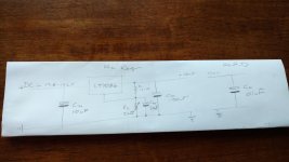
No problem since CD is just a low HF impedance local measure to decouple the incoming wires inductance for avoiding CCS oscillation.
Hello,
I completed my first R-D with success, it took place of an Bib in powering 8v\160mA. supply for a DAC. It is one only ic Philips TDA1543.
Sound is diffenent, how to say... R-D is prefered, easy to listen, but all components brand new simply can't deliver as much 'detail' as the fully broken in Bib unit.
No need to say, I appreciate so much advice here🙂, and wants share also my own findings. -despite my limited English and electronic knowleadge.-
Concerning CM cap, as stated before, I agree to be very influential to final sound. But not only in brand ALSO in value. After arranging an array of caps. I have on hand:
-10.000uf. Nichicon FW
-4.700uf. Nichicon KG
-2.200uf. Elna Silmic II
-1.000uf. Nichicon KZ
The negative leg is tied both toghether and soldered to neg on pcb.
Then the + leg is free, keeping to easy swap with a cocodrile wired to Pcb still when music is playing.
In first was a play for the bigger 10.000 as specs in diagram, but soon enters the play, as much as I decreases the capacitance it is increase the detail in sound. Till finally reaching the small 1.000uf. which removes completelly the loudness related of excess capacitance. But nothing thin, otherwise great strenght in overall frecuencies including clean punch bass notes. I have experienced this in many circuits, as in Bib one for instance, where its recommended main cap. 4.400uf., decreases for me till 1.000uf - 1.500uf . I use nothing but Nichikon Muse KZ, however by using non audio grade capacitors, must prefer higher filtering value as in schematic diagram. I barely remember but reading somewhere or heard that audiophile electrolitic capacitors not direct replacement by same value.
Once found the value by hearing, it's a nice, very nice addition upgrade then to CLC.
Although bulky and expensive, this solution is worth the effort, as it transforms the sound to another league. Is needed another capacitor, same value, and a choke in between wired in series with + rail. I use 10H amorfe big choke, other cheaper choke, less quality iron or filtering amount, not same results.
- Home
- Amplifiers
- Power Supplies
- Reflektor-D builds