Great work Salas!
My prayers for 4-pin has been heard 🙂
JFet instead of resistor is a must for me as well.
The only thing missing here would place for Finemet Beads, but this can be fitted between dc-out from flexy into dc-in Reflector D mini.
Thanks!
My prayers for 4-pin has been heard 🙂
JFet instead of resistor is a must for me as well.
The only thing missing here would place for Finemet Beads, but this can be fitted between dc-out from flexy into dc-in Reflector D mini.
Thanks!
Finally the Reflektor-D Mini is ready and the description pdf is attached.
A little raw DC companion board that can use common two pole reservoir capacitor as well as Mundorf four pole -without any modifications needed- is ready too. I have named it DC Flexy 🙂
Read it to tell me if its understandable text or you need some clarifications. BTW the PCBs print is not very nice yet because they are just test boards.
Amazing work, Reflektor-D Mini dressed as BiB (black in black)😀
I don't know exactly when Tea will make some next GB. I consider them finished technically. So better ask Tea.
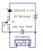
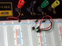
Example on the test jig
As you have seen there is a simple test jig proposed in the Mini pdf to help predefine Vref components Vf in conjunction with any J2 IDSS at hand. Since the big Ref-D is many times used with J2 also instead of R6 depending on preference I thought it would be nice I explain it a bit more.
What we see in the schematic is a 9V battery, a 5.1V Zener, a J2 2SK117GR JFET with its G & S pins shorted, a Led to test for Led1 or Led2 positions. They are all in line forming a DC loop. A DMM measures the Led's forward voltage drop across it.
By dropping the battery voltage with the Zener to about 4V minus the Led's Vf we come closer to what voltage J2 will see across when in circuit by M2's VGS and to what final IDSS it will produce when there.
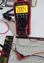
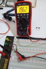
In the pictures we see one same green Led that I randomly picked from a no name bag being measured for Vf with two different random J2 in the jig. The difference of Led Vf due to different enough J2s IDSS is evident. A third J2 was resulting much nearer Vf to the first though. That means it had closer IDSS to the first but we don't care to know their IDSS. Even with a single J2 at hand we can just change Leds or add Rx/J/D to reach the voltage we target anyway. 🙂
If Leds and jumper only don't make our target and we need add D or Rx for some substantially more Vout or in-between, we test Rx or D in the Led's place also to know what they contribute with our specific J2. But we better avoid adding components when near enough target.
Using the 2.004V Led and a jumper it would give me 3.22V Vout for instance after adding the 1.22V current mirror BJTs standard contribution. I would prefer to look for a stronger green Led so to go nearer 3.3V with just jumper than to seek a small resistor, something like 15R, to see if it can give me 0.08V extra in the jig. Even if I could not find a stronger Led, usually 3.22V will be in spec for any 3.3V chip and I will still avoid the resistor. Less components is simpler Vref. D is preferable to Rx where possible. More predictable.
Since that same J2 will end up in the build we expect the tested Led(s) to encounter its same current and to show the same Vf. With some allowance for practical differences due to various M2 and non exact voltages of course.
So no need to worry about what J2 IDSS characterization to initially pick or to must having more than one. 🙂
As you have seen there is a simple test jig proposed in the Mini pdf to help predefine Vref components Vf in conjunction with any J2 IDSS at hand. Since the big Ref-D is many times used with J2 also instead of R6 depending on preference I thought it would be nice I explain it a bit more.
What we see in the schematic is a 9V battery, a 5.1V Zener, a J2 2SK117GR JFET with its G & S pins shorted, a Led to test for Led1 or Led2 positions. They are all in line forming a DC loop. A DMM measures the Led's forward voltage drop across it.
By dropping the battery voltage with the Zener to about 4V minus the Led's Vf we come closer to what voltage J2 will see across when in circuit by M2's VGS and to what final IDSS it will produce when there.
In the pictures we see one same green Led that I randomly picked from a no name bag being measured for Vf with two different random J2 in the jig. The difference of Led Vf due to different enough J2s IDSS is evident. A third J2 was resulting much nearer Vf to the first though. That means it had closer IDSS to the first but we don't care to know their IDSS. Even with a single J2 at hand we can just change Leds or add Rx/J/D to reach the voltage we target anyway. 🙂
If Leds and jumper only don't make our target and we need add D or Rx for some substantially more Vout or in-between, we test Rx or D in the Led's place also to know what they contribute with our specific J2. But we better avoid adding components when near enough target.
Using the 2.004V Led and a jumper it would give me 3.22V Vout for instance after adding the 1.22V current mirror BJTs standard contribution. I would prefer to look for a stronger green Led so to go nearer 3.3V with just jumper than to seek a small resistor, something like 15R, to see if it can give me 0.08V extra in the jig. Even if I could not find a stronger Led, usually 3.22V will be in spec for any 3.3V chip and I will still avoid the resistor. Less components is simpler Vref. D is preferable to Rx where possible. More predictable.
Since that same J2 will end up in the build we expect the tested Led(s) to encounter its same current and to show the same Vf. With some allowance for practical differences due to various M2 and non exact voltages of course.
So no need to worry about what J2 IDSS characterization to initially pick or to must having more than one. 🙂
Attachments
I don't know exactly when Tea will make some next GB. I consider them finished technically. So better ask Tea.
Thank Salas😉
Awesome work on the Reflektor-D Mini and Flexy, Salas!
Do you have any plans to incorporate support for four pole reservoir capacitors and snubber parts into the standard Reflektor-D?
In your opinion is anything lost having the rectification on a separate board and moving to two wire output? I'd love to try a Mundorf AG+, but wouldn't want to sacrifice performance elsewhere since space savings isn't a priority.
No such plans right now as they increase bulk to the bigger Reflektor. I did those additions separately given the opportunity. A small bit is lost when having a two wire output and long distance. Given there is no interference with four wire connection in the same situation. But we made the Mini for being able to go very near. The big Reflektor takes DC input also if there is space for raw DC separately and the on-board sinking is preferable, so it can be combined with a Flexy as well for someone having Mundorf.
Thanks Salas, that makes sense.
Realized right after I posted that the standard Ref-D also has DC-in capability that will work with the Flexy! I'm guessing that by placing the Flexy right up against the Ref-D (keeping lines as short as possible) and twisting the wires, you wouldn't loose anything over having everyone on one board?
I did think of another scenario that I wanted to run by you. With a different project I want to power two boards with one Ref-D -- in a case like this, how would you recommend running the sense lines? Or, would it be better to use the Ref-D Mini with two wire output and run separate lines to each board from there?
No you wont lose anything with relatively short raw DC cables especially and remember to put the "Cd" DC input decoupling film cap on the big Ref-D when feeding it DC.
You got choices on the Big. You can revert it in two wire mode too. Which is safer in weird configurations. I would jumper S+ to F+ and 0 to 0 with short insulated wires right under the output connector to make it two wire mode first. Then I would bring thick enough but manageable and reasonably short +/0 wires from each client board to the + and 0 output connector's screws. There will be two 0 connector screws and two + connector screws available doing the same respective job now. Perfect for neatness to cater for two load boards i.e. two pairs of power wires total.
You got choices on the Big. You can revert it in two wire mode too. Which is safer in weird configurations. I would jumper S+ to F+ and 0 to 0 with short insulated wires right under the output connector to make it two wire mode first. Then I would bring thick enough but manageable and reasonably short +/0 wires from each client board to the + and 0 output connector's screws. There will be two 0 connector screws and two + connector screws available doing the same respective job now. Perfect for neatness to cater for two load boards i.e. two pairs of power wires total.
Thank you Salas, super helpful. Appreciate you taking the time to answer my questions.
Looking forward to picking up a pair of Flexy boards during the next group buy!
Looking forward to picking up a pair of Flexy boards during the next group buy!
salas I have a question regarding this 3.3V reg as I see the Reflektor D is giving same current at the both legs of the mirror but how is it different from the other circuits like this?
http://www.datasheetdir.com/circuit...gulation-For-Ultra-low-Noise-Applications.jpg
The noise level in the above circuit is said to be on -160db.
out of curiosity just wanted to know the difference between the above circuit and the reflektor D
http://www.datasheetdir.com/circuit...gulation-For-Ultra-low-Noise-Applications.jpg
The noise level in the above circuit is said to be on -160db.
out of curiosity just wanted to know the difference between the above circuit and the reflektor D
Hi guys,
Need help from you. I'm building a Red Baron DAC that will be powered by Reflektor-Ds.
Regarding powering the shunts, I need a little bit of help, for the voltage-current ratings:
power req. transf. specs. shunt reg. current
WaveIO 5V-500mA (9VAC 1A) 700mA (Reflektor-D)
Vdd 5V-40mA (9VAC 0.5A) 200mA (Reflektor-D)
-Vdd1 -5V-50mA (9VAC 0.5A) 200mA (Reflektor-D)
-Vdd2 -15V-35ma (20VAC 0.5A) 200mA (BiB negative)
Vd1 3.3V-50mA (9VAC 0.5A) 200mA (Reflektor-D)
Want to order a toroidal/R-core transf. and I need to be sure about the ratings.
If I use 5 different tranformers and put them in parallel,would be a problem?
Kind regards,
Alex.
salas I have a question regarding this 3.3V reg as I see the Reflektor D is giving same current at the both legs of the mirror but how is it different from the other circuits like this?
http://www.datasheetdir.com/circuit...gulation-For-Ultra-low-Noise-Applications.jpg
The noise level in the above circuit is said to be on -160db.
out of curiosity just wanted to know the difference between the above circuit and the reflektor D
They are totally unrelated topologies. The one you linked is a series regulator with a Zener voltage reference U1 amplified by an op-amp U3. The chip compares ref to output voltages on its +/- inputs and drives the pass transistor Q1. As a whole it is relying on very many transistors when counting the op-amp's internals.
The Reflektor is a minimalistic regulator with input current limiter and a unity gain reference (i.e. the Leds are not amplified). It reacts to input vs output side current disturbance through a current mirror who's purpose in life is to remain balanced for current between its sides. Its components count is super low, what you see is what you count. The rail CCSed shunt keeps the currents summing at its output node where the series pass represents them all the way back to the raw DC components and transformer. There is nothing between the current limiter and the load also because its a shunt.
I don't say that the one you linked is not achieving its purposes, all I am describing is that they are derived from different philosophies and practices. Many ways to skin a cat. I am a minimalist when I can.
Hi guys,
Need help from you. I'm building a Red Baron DAC that will be powered by Reflektor-Ds.
Regarding powering the shunts, I need a little bit of help, for the voltage-current ratings:
power req. transf. specs. shunt reg. current
WaveIO 5V-500mA (9VAC 1A) 700mA (Reflektor-D)
Vdd 5V-40mA (9VAC 0.5A) 200mA (Reflektor-D)
-Vdd1 -5V-50mA (9VAC 0.5A) 200mA (Reflektor-D)
-Vdd2 -15V-35ma (20VAC 0.5A) 200mA (BiB negative)
Vd1 3.3V-50mA (9VAC 0.5A) 200mA (Reflektor-D)
Want to order a toroidal/R-core transf. and I need to be sure about the ratings.
If I use 5 different tranformers and put them in parallel,would be a problem?
Kind regards,
Alex.
If its OK putting many transformers primaries parallel to the mains is correctly what I think you ask, then yes its OK.
If with a single custom made transformer with all those secondaries you need in your list it should be roughly 35W constant power needed in total so get an 80VA core spec.
Hi Salas, can the reflektor-d mini handle output approx +8v? If so, what is the overhead needed for the input voltage?
Thanks,
James
Thanks,
James
Yes. A practical way for that is to use LM329 instead of led1 and short led2. That low noise/low impedance voltage reference part must be oriented with its cathode opposite to be using an led. Has 3 pins but one is not connected inside and you can trim it. Rx/j/d shorted with a jumper too. You should get 8.12 to 8.3V output. Use 12V AC transformer.
Excellent news, thank you 🙂Yes. A practical way for that is to use LM329 instead of led1 and short led2. That low noise/low impedance voltage reference part must be oriented with its cathode opposite to be using an led. Has 3 pins but one is not connected inside and you can trim it. Rx/j/d shorted with a jumper too. You should get 8.12 to 8.3V output. Use 12V AC transformer.
To come in at just under 8v will 3 green leds work the best? In my application, it is better to be a little lower voltage than a little higher.
In order to get 8v dc out, what is the minimum dc input for the reflektor-d mini?
Thanks again,
James
- Home
- Amplifiers
- Power Supplies
- Reflektor-D builds