You really should listen to SEN I/V with the BIII ...it's a completely different ball game.
Really? I use Legato without output caps and I'm very satisfied with the SQ. There is a GB or where have I to order the pcb & parts?
Really? I use Legato without output caps and I'm very satisfied with the SQ. There is a GB or where have I to order the pcb & parts?
Yep...tried both and i can tell you there is no contest in my opinion.
Contact XEN website for PCBs....bear in mind you will need battery floating supplies.
needless to say i never went back to legato.
Can't be powered without batteries?
How much cost?
Batteries are a must because of noise...quite a few very good power supplies have been tried and batteries come out on top, anyway using rechargeables with the simple charger circuit EUVL has published means they will last many years .
cost of PCBs are very affordable...very small ...check XEN website.
You really should listen to SEN I/V with the BIII ...it's a completely different ball game.
It certainly would be a different ball game as I wouldn't be able to drive long interconnects as well or use my headphones without other modules, however, remembering that this is a Reflektor-D build thread, I did follow up on your suggestion; the XEN website isn't very helpful and I couldn't find the SEN/CEN board prices, though I did find links to some very long discussion threads, so, at least for now I will continue with my roadmap.
Ray

If it can't be powered with a Salas shunt regulator, I'm not much interested. 🙂
I uses many salas shunt regs but if you have not heard the SEN then we cannot discuss much.....hearing is believing in this case ....this ofcourse is just my opinion.🙂
Anyway i will close this topic now because this is the Reflektor D thread....of which i have built 4 so far.
They are fantastic and have very little drift as well, typically about 0.06 V in my case....on all 4 of them.
Last edited:
Given the very low component count especially in Vref and the high dissipation, such drift is practically very comfortable.
Very nice reg design.
Salas, you have my congrats!
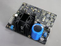
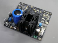
Here my effort!
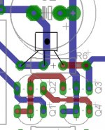
The voltage was 5.018 with R6, that increased a bit with 2SK117 fet to 5.19 For this reason, I putted a series of pins at the position of R6, for easy acoustic estimated to my tests.
Two green leds are used.
The voltage drop on the R1 was 0.6164 that means almost 411mA total current (dac load). The R1 value was 1.5R (Caddock MP930).
The temperature at the opposite of M2 (sensor at the M2's heatshink, internal area of two heatshinks),was 42-43°C after 1 hour operation.
Salas, you have my congrats!
Here my effort!
The voltage was 5.018 with R6, that increased a bit with 2SK117 fet to 5.19 For this reason, I putted a series of pins at the position of R6, for easy acoustic estimated to my tests.
Two green leds are used.
The voltage drop on the R1 was 0.6164 that means almost 411mA total current (dac load). The R1 value was 1.5R (Caddock MP930).
The temperature at the opposite of M2 (sensor at the M2's heatshink, internal area of two heatshinks),was 42-43°C after 1 hour operation.
Attachments
Very nice build and pics lemon, congratulations. How was the drift BTW? Stayed well put after warm up?
P.S.
Lets refresh the readers on what you do there with the pins and the FET in the R6 position. You are trading better (lower) Zo for wee bit more noise and less than half the flat Zo bandwidth due to an active CCS part vs 1k resistor. And you will subjectively evaluate that for your DAC. Alternating between a low ppm resistor and a midrange idss 2SK117GR. Based on a suggestion for different evaluations I made in the Ref-D GB thread posts #68 & 71.
Thanks Salas.
The drift, what is this?
I haven't any significant drift after warming period, sometimes changes the last 3rd digit by one!
If I measured at the cold start immediately, then this is 5.22 and after the "warming" it is stabilized to the 5.19
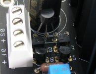
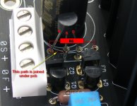
What I have doing here, is what I have read at the posts that you have note. I upload a capture for better understanding.
To my dac, seems the fet has a better acoustic sound.
At the position of R6 (1K) there are some female pins. The right position seems to my capture (G+S joined to the ground).
It is a easy way to try with R6 or fet between my listening tracks or to different dacs.
The drift, what is this?
I haven't any significant drift after warming period, sometimes changes the last 3rd digit by one!
If I measured at the cold start immediately, then this is 5.22 and after the "warming" it is stabilized to the 5.19
What I have doing here, is what I have read at the posts that you have note. I upload a capture for better understanding.
To my dac, seems the fet has a better acoustic sound.
At the position of R6 (1K) there are some female pins. The right position seems to my capture (G+S joined to the ground).
It is a easy way to try with R6 or fet between my listening tracks or to different dacs.
Attachments
Last edited:
Difficult answer for someone that the English language aren't very well.
I have tried at this dac (mambo2) a lot of psu (LM317, TI TPSA4701EVM, Salas BiB, e.t.c).
I must to say that this dac, has a lot of local dc-dc regs and needs an initial psu to feed all of these.
For this dac, the reflektor and the TI evb seems to hi from the begging.
After some carefully acoustic estimation, the reflektor was the winner for this dac.
More voice sound depth, harmonics was there...at the classic or live jazz tracks some music organs have more area at the music scene.
Don't push me any more with words, I can't find any better describing..
Do you believe that you will have better jitter if you change the initial psu of a dac?
Don't you?
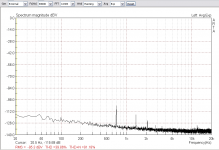
Look at the following captures, carefully.
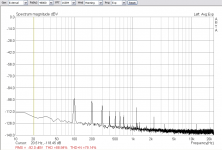
The role of digital generator held from the Altor JGEN-384, the role of signal capture held from the EMU-0404 (usb). The signal and the capture was 24/48KHz.
The test was done on 9023 based dac (through spdif), that including many local dc-dc converters. This dac including also an initial PSU on a SemiOn 7805 (smd) with almost total 2000uF capacitance before and after the MC7805.
Look as the noise floor as a jitter captures. There are some interferences around 100Hz and the harmonics of this frequency (Noise Floor Test).
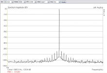
Around the 12KHz base frequency, there are some sidebands frequencies due increased jitter (Jitter Test).
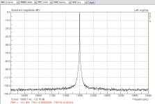
The things are changed with Reflektor-D initial PSU.
The noise floor is clean, except some peaks due dac design (probably) and the jitter sidebands have gone!
Wonderfull results from a wonderfull PSU.
Thanks Salas.
Don't you?
Look at the following captures, carefully.
The role of digital generator held from the Altor JGEN-384, the role of signal capture held from the EMU-0404 (usb). The signal and the capture was 24/48KHz.
The test was done on 9023 based dac (through spdif), that including many local dc-dc converters. This dac including also an initial PSU on a SemiOn 7805 (smd) with almost total 2000uF capacitance before and after the MC7805.
Look as the noise floor as a jitter captures. There are some interferences around 100Hz and the harmonics of this frequency (Noise Floor Test).
Around the 12KHz base frequency, there are some sidebands frequencies due increased jitter (Jitter Test).
The things are changed with Reflektor-D initial PSU.
The noise floor is clean, except some peaks due dac design (probably) and the jitter sidebands have gone!
Wonderfull results from a wonderfull PSU.
Thanks Salas.
Attachments
Very interesting captures Lemon. Are those local dc-dc chips in the various DAC subsystems, linear regulator SMD chips?
Yes Salas.
Two Texas Instruments TPS7A4901DGNR (12.7μVrms, 20-20KHz) UltraLowNoise Linear Regulators for Wolfson receiver, clocks and Sabre 9023 and an ON-Semi NCV551SN50T1G for multiplexer.
Two Texas Instruments TPS7A4901DGNR (12.7μVrms, 20-20KHz) UltraLowNoise Linear Regulators for Wolfson receiver, clocks and Sabre 9023 and an ON-Semi NCV551SN50T1G for multiplexer.
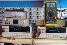
Just got my two Reflektor supplies working on the bench with the test resistor load included with the kits. Both worked first time, with no assembly problems.
Two green leds for 5.1V
Two green leds and a 56R resistor for 5.22V
Nominal 9V transformer.
Both seem to be rock steady.
Just need to finish the rest of the DAC now!
Thanks Salas and Tea-Bag.
Ray
Two green leds for 5.1V
Two green leds and a 56R resistor for 5.22V
Nominal 9V transformer.
Both seem to be rock steady.
Just need to finish the rest of the DAC now!
Thanks Salas and Tea-Bag.
Ray
 Let us know when applied.
- Home
- Amplifiers
- Power Supplies
- Reflektor-D builds