Hello Salas,Something must be wrong. Its not normal to get that same higher than expected voltage with three different combinations of just one LED. Maybe the output MOSFET or some transistor has a problem. Check every Vgs and every Vbe, let us know their values. If by putting back the resistor that has been replaced by the JFET mod Vout goes back to normal predictions then other semis could not be broken but the the mod could have been applied wrongly.
I have 3 custom(with only JFET mode possibiity) Reflektor-D PCB so I have tried to put only one led on another board to remove the ideea of the output MOSFET problem.
Another board, 1 yellow LED - 4,48V output
Vgs M2 ~3V
Vgs M1 ~ 7V
Vbe on Q1,2,3,4 ~ 0,6V
I check the JFET mode connection: drain to R4, source and gate to GND
Hello Salas,
I have 3 custom(with only JFET mode possibiity) Reflektor-D PCB so I have tried to put only one led on another board to remove the ideea of the output MOSFET problem.
Another board, 1 yellow LED - 4,48V output
Vgs M2 ~3V
Vgs M1 ~ 7V
Vbe on Q1,2,3,4 ~ 0,6V
I check the JFET mode connection: drain to R4, source and gate to GND
Please discard the above measurements I made a second and more precise measurements:
Another board, 1 yellow LED - 4,48V output
Another board, 2 yellow LED - 5,25V output, with the next measurments:
Vgs M2 - 3,80V
Vgs M1 - 7,30V
Vbe on Q1,2,3,4 - 0,67V
Vgs appears between the two outer legs of such Mosfets. Are you sure its not something different what you measured? Because its too high for M2 MTP3055VL which is a low threshold type and too much for M1 IRF9610 also if the normal currents of the design are involved. Vbe are alright.
Vgs appears between the two outer legs of such Mosfets. Are you sure its not something different what you measured? Because its too high for M2 MTP3055VL which is a low threshold type and too much for M1 IRF9610 also if the normal currents of the design are involved. Vbe are alright.
Hello Salas,
Yes I measure it across the outer legs.
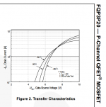
I use 8,4V input voltage, 1ohm R1, 33ohm test load resistor, FQP 3N50C as M2 and FQP 3P20 as M1
FQP3N50C is wrong to use there, it won't allow 3.3V output. Its a normal Vgs threshold Mosfet. Use the original BOM's M2 type first of all.
You are right Salas, I omitted that because originally I have use all 3 boards for 5V and 8V .FQP3N50C is wrong to use there, it won't allow 3.3V output. Its a normal Vgs threshold Mosfet. Use the original BOM's M2 type first of all.
 Talking about that, is FQP 3N50C enought for 5,25 V output? It seems that 3,8 Vgs is on the edge.
I put MTP3055VL in the M2 place and now with a green LED I get 3,27V output 😎
The other measurments are: Vgs M1 6.00V and Vgs M2 2,10 V
Now the Vgs are ok?
FQP3P20 you use for M1 shows about -6V Vgs at 0.5 to 0.6A drain current in its datasheet depending on its temperature, batches and samples also differ, so your reading is OK since your one Ohm resistor should be having ~0.6V across it. In other words setting circa 0.6A CCS. M2's Vgs is alright also.
Attachments
The 3N50C uses up more voltage than the 3055 would but at 5.25V output and 3.8V Vgs there is still marginal threshold to the mirror transistors for the reg to keep its spec.
Thank you Salas for your support !
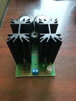
This is how my boards looks like, I am very please with your design.
This is how my boards looks like, I am very please with your design.
Thank you Salas for your support !
This is how my boards looks like, I am very please with your design.
You are welcome. Better upload pictures as attachments on our server for all without special permissions to see and to surely remain.
There you go 🙂
EDIT: could you please remove the links I posted before, or better to merge the two post in to one?
Thank you !
EDIT: could you please remove the links I posted before, or better to merge the two post in to one?
Thank you !
Attachments

Last edited:
 I just removed the links.
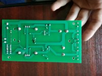
Own design boards Using CLC pre-filter and 2wire output scheme only I believe?
Thank you !
Own design boards Using CLC pre-filter and 2wire output scheme only I believe?
Yes you are correct ! 😀
What's on the small third sink? A thick film ceramic back CCS setting resistor?
It is a TO-220 style resistor
I have two boards with 1ohm Bourns resistor and one with 0,75 ohm Caddock.Caddock?
I know that Caddock is better but I can't find it in EU, so for testing purpose I use Bourns.
I use the 0,75 one for powering a BBB but the LED's is still flickering. I will try to turn of the BBB HDMI and maybe USB port to reduce power consuming, and if that isn't enough I will increase the CCS even more 🙁
I have two boards with 1ohm Bourns resistor and one with 0,75 ohm Caddock.
I know that Caddock is better but I can't find it in EU, so for testing purpose I use Bourns.
I use the 0,75 one for powering a BBB but the LED's is still flickering. I will try to turn of the BBB HDMI and maybe USB port to reduce power consuming, and if that isn't enough I will increase the CCS even more 🙁
I manage to disable the BBB HDMI and now the LED's on the board with 0.75ohm CCS is flaring only for 2 seconds when the BBB boot, even if I measure a maximum 460mA power consuming on boot. Despite that I am happy that now I can use the Reflektor-D with my BBB and the output voltage doesn't drop anymore.
What resistor load size I should use on this particular board so that I don't influence the performance of the regulator and if I shut down the BBB by mistake the Reflektor-D will not damage for not having a load ?
Attachments

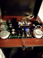
Put the DMM in Min-Max mode during boot. Maybe it can better capture the short current consumption peaks that are surely there. An oscilloscope over a sense resistor is best for that. The REF-D does not suffer electrical damage when not having a load. All the available current from the CCS is burned by the output MOSFET sending it to ground. It will just make its sink hotter, so if you see its too hot don't let it idle for very long without a load, power the PSU down. If you want to keep it idling for some reason just switch on a near 500mA dummy to its output like a 6.8 Ohm 5W resistor for 3.3V.
- Home
- Amplifiers
- Power Supplies
- Reflektor-D builds