The best mode is locating the regulated PSU on top of the power input pins of the receiving circuit.
Then it makes no difference whether you use local, or remote sensing.
Interesting, I'll see if I can set that up
The Mini version is small so to can go near. Uses classic two wire output. If you can use no more than 5cm of 12 AWG cable it will be very nice. Longer is not reactionary just more mΩ.
Four wire output in the big version has not a burden of output wires length vs added resistance but the inductance of the sense cables and the extra loop area they create must not allow for instability or interference problems. That should be monitored in any build that has different client circuit load, distance, wire dressing, and RFI presence, so there is no defined max length answer. Only guidelines.
Keep Kelvin four wire not longer than necessary, twist sense wiring well, and verify the rail stability with a scope.
Hi,
I'm considering changing power supply of my DAC based on old R2R 4xPCM1704 BB chips.
I need:
+5V and -5V DC for digital part and
+5V and -5V DC for analog.
I thought that for digital (positive and negative) I could use 2xREF-D.
Is it a good idea to use REF-D as negative voltage source?
What about analog positive and negative power supply. Is BIB v2 could be a good choice for my DAC?
I have two spare 'center tapped' transformers (8VAC). Can use these transformers and single bridge for supply symmetrical (positive, negative) voltage to 2x Ref-D (digital) and BIB (analog) +/-5VDC?
 Is there any advantage/disadvantage of that approach (tapped transformer and single bridge) in respect to supplying REF-D and BiB?
Regards,
I'm considering changing power supply of my DAC based on old R2R 4xPCM1704 BB chips.
I need:
+5V and -5V DC for digital part and
+5V and -5V DC for analog.
I thought that for digital (positive and negative) I could use 2xREF-D.
Is it a good idea to use REF-D as negative voltage source?
What about analog positive and negative power supply. Is BIB v2 could be a good choice for my DAC?
I have two spare 'center tapped' transformers (8VAC). Can use these transformers and single bridge for supply symmetrical (positive, negative) voltage to 2x Ref-D (digital) and BIB (analog) +/-5VDC?
Regards,
Ref-D although positive in itself can also be arranged to a good virtual minus regulator when used in pairs. But to make +/- outputs from two positive regulators it takes four wire independent secondaries from the transformer and double bridges. As in the attachment. Can't use center tap and single bridge as with dedicated minus regulators. BiB on the other hand has a real negative section that can be used with center tap and single bridge if its own diode bridges will be skipped and proper linking between its positive and negative section main filter capacitors will be made.
Attachments
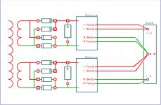
Thank you very much Salas.Ref-D although positive in itself can also be arranged to a good virtual minus regulator when used in pairs. But to make +/- outputs from two positive regulators it takes four wire independent secondaries from the transformer and double bridges. As in the attachment. Can't use center tap and single bridge as with dedicated minus regulators. BiB on the other hand has a real negative section that can be used with center tap and single bridge if its own diode bridges will be skipped and proper linking between its positive and negative section main filter capacitors will be made.
Do you think that two 2x8VC transformers (2x(11-12V) DC after rectification) will be sufficient to supply +/-5V DC from 2xRef-D and BiB to DAC chips?
Regards,
Bern
That's typically enough margin but to avoid shortening it too much when the mains will fall by few Volt at weak grid hours better use Schottky rectifier diodes that have low intrinsic voltage loss.
Even 7.5VAC is enough, if you use proper (outsized power) transformer and good rectifiers.
I use 7.5VAC 40VA transformer for 0.5A raw supply.
The current load on the transformer is about 1A RMS (2.9A peek).
The graetz rectifiers are MBR1635 Schottky diodes (0.73A RMS, 2.9A peek, 90mW dissipation), the first capacitor is 10mF (0.9A/2.4A ripple), the raw voltage is 9.1V (at 0.5A load).
If you use SiC rectifiers, the output is 7.9V (it's on the border for 5V Reflektor) and the diodes dissipation is 200mW!
can reflektor be powered using 9V at the regulator input and expect 3.3V in the output?
Yes
Hi,
Could CRC filter after the diodes bridge (lets say 10mF-2ohm-10mF) could bring any audible benefits for 5V DC/600mA output?
Regards,
Bern
Could CRC filter after the diodes bridge (lets say 10mF-2ohm-10mF) could bring any audible benefits for 5V DC/600mA output?
Regards,
Bern
Hello 🙂
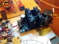
just to share my new 5v build.
This time with mundorf ag + elna silmi ii + vishay1837 with caddock mp930 (r1). i miss the r6 var but when i get i will put in place...
As usually the sound quality is astounding 🙂
this i was using a chinese power supply with opamp based on studer900 ps (that people rave about on forums).
it was not bad but when i change to reflektor... the sound improved once again..
i want to try other cap combinations to see if i feel so much difference in sound between them.
The highs are so clear and i feel every atmospheric nuances in music. the bass and dynamics are impressive too...for me is just the best i have heard.
Thanks once again Salas!
Attachments
Hi,
Could CRC filter after the diodes bridge (lets say 10mF-2ohm-10mF) could bring any audible benefits for 5V DC/600mA output?
Regards,
Bern
I tried a simulation with CRC and resistor R=3,3ohm. It doesn't look bad.
One thing concern me. Is 9,4V DC Vin will be enough for Ref-D with Vout=5V DC?
Attachments
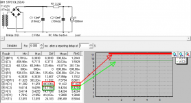
Not to drop out, yes it will be enough. Since some 100Hz rectification ripple will be eaten out by the filter, you got more leeway. For example in a target of 10VDC+AC at the last E Cap when 1V of that is ripple then 9V pure DC target is an equivalent.
Thank you Salas.
During experiments I probably damaged one of my Ref-D :-(
I had One green LED, JFET mod and about Vout=3.3VDC
But now the LED not lit.
I measured voltages:
On the reservoir capacitor I have 11,2V DC
On output 2,57V and on LED 1,5 V
What should I check and how could I fix this?
Thanks,
Bern
During experiments I probably damaged one of my Ref-D :-(
I had One green LED, JFET mod and about Vout=3.3VDC
But now the LED not lit.
I measured voltages:
On the reservoir capacitor I have 11,2V DC
On output 2,57V and on LED 1,5 V
What should I check and how could I fix this?
Thanks,
Bern
First make sure there is no overloading on the output that brings the CCS to limiting so the output voltage drops. Then check every Vgs and every Vbe. Then the RDS of JFETS.
hi Salas,
it's been a long delayed project. life's getting in the way.
i'm trying to build 12 volts ref-d using LM329 as per your suggestion.
right now i use LM329 on led 1 position and 2 green LEDs for the rest.
but the LEDs don't shine. 20.8 volts on CM and no voltage on C2.
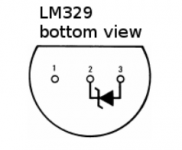
i removed the 1st leg of LM329 and connected 2nd leg on anode position of led 1 and 3rd leg on cathode. could this be the culprit ?
it's been a long delayed project. life's getting in the way.
i'm trying to build 12 volts ref-d using LM329 as per your suggestion.
right now i use LM329 on led 1 position and 2 green LEDs for the rest.
but the LEDs don't shine. 20.8 volts on CM and no voltage on C2.
i removed the 1st leg of LM329 and connected 2nd leg on anode position of led 1 and 3rd leg on cathode. could this be the culprit ?
LM329's pin2 should go where a LED's anode would be and you did it correctly. Because it works in opposite orientation like a Zener not like an LED. Maybe you had mistaken its correct facing pin order between top view and bottom view. If not, test the two LEDS are correctly positioned and functioning. Briefly touching their pins with wires from a 9V battery or probe them with a DMM's diode test (if its >2V able). No need to remove them from the PCB for that.
Attachments
- Home
- Amplifiers
- Power Supplies
- Reflektor-D builds