PSU almost done
Hi Oliver
at first I want to thank you and Salas for availability of solutions as schematics and boards.
I know that TDA1541 is excellent "sound maker", so this project is very promising.
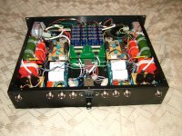
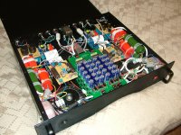
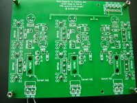
Next, at last I finished my PSU box - you can see photos in attachment.
It is 2U 19" rackmount box.
Here are two sets of LV and HV outputs for dual mono TDA1541 DAC and two tubed stages after it -2 x (25VDC, 20VDC, 17VDC, 300VDC and 11VDC) outputs.
Transformers are three per channel: one 65W from Analogmetric (0-12-15-18-24VAC[1A] x2, 9VAC[1A]x2), one 30VA Amplimo type 17070 (2x115VAC [0.13A]) and one TALEMA 25VA (9VAC[1.38A]x2).
All outputs were tested with load - LV outputs with 200mA load (first dummy load, later Salas shunts were connected) and HV output - with dummy load (about 40mA). Outputs for tube heating were tested with 2A dummy load.
Now I can continue assembling DAC box (3U). Almost all Salas shunt regulators completed - still waiting for few SK170 to be delivered.
By the way, one of LV regulator (-15VDC) is non operational - I can not set output voltage - input is -24.8VDC, output - always about -9.4VDC.
I have measured voltages in another regulator (it is ok) and compared those with non operational regulator's voltages.
In working regulator BC560 base has -0.628VDC on it, in broken - 0 VDC. Maybe SK170 or BC560 is broken. Any ideas?
Saulius
Hi Oliver
at first I want to thank you and Salas for availability of solutions as schematics and boards.
I know that TDA1541 is excellent "sound maker", so this project is very promising.
Next, at last I finished my PSU box - you can see photos in attachment.
It is 2U 19" rackmount box.
Here are two sets of LV and HV outputs for dual mono TDA1541 DAC and two tubed stages after it -2 x (25VDC, 20VDC, 17VDC, 300VDC and 11VDC) outputs.
Transformers are three per channel: one 65W from Analogmetric (0-12-15-18-24VAC[1A] x2, 9VAC[1A]x2), one 30VA Amplimo type 17070 (2x115VAC [0.13A]) and one TALEMA 25VA (9VAC[1.38A]x2).
All outputs were tested with load - LV outputs with 200mA load (first dummy load, later Salas shunts were connected) and HV output - with dummy load (about 40mA). Outputs for tube heating were tested with 2A dummy load.
Now I can continue assembling DAC box (3U). Almost all Salas shunt regulators completed - still waiting for few SK170 to be delivered.
By the way, one of LV regulator (-15VDC) is non operational - I can not set output voltage - input is -24.8VDC, output - always about -9.4VDC.
I have measured voltages in another regulator (it is ok) and compared those with non operational regulator's voltages.
In working regulator BC560 base has -0.628VDC on it, in broken - 0 VDC. Maybe SK170 or BC560 is broken. Any ideas?
Saulius
Hi Saulius,
i can´t see the TDA1541A Shunt module on your photos. It will help if you could shoot some detailed photos of the reg. pcb.

Hi Saulius,
i can´t see the TDA1541A Shunt module on your photos. It will help if you could shoot some detailed photos of the reg. pcb.
Hi Oliver,
here are attached few photos:
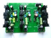
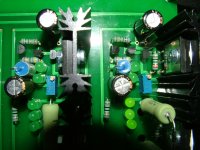
1 - this is operational SSLV -15V, -25V only connected (LED are bright on left side);
2 - broken SSLV -15V, -25V connected at right side (LED are lit on right).
On right side because all layout of components are mirrored. But mirroring is not problem - same layout -5V shunt is operational even if difference between -15V and -5 SSLV is only in trimmer value;
3 - bottom side of broken SSLV.
Data of measuring will be next message, as I can not attacth more than 3 pics here.
Attachments
Here is more pics:
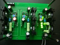
1 - near shot of shunt stage;
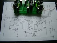
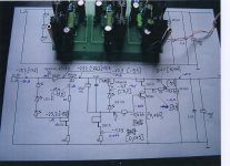
2 - my measurings on paper - values without brackets are from normal SSLV, in brackets - from broken SSLV.
By the way both IRFP240 in broken regulator are warm as in normal regulator - total consumption of current is about 130mA.
Saulius
1 - near shot of shunt stage;
2 - my measurings on paper - values without brackets are from normal SSLV, in brackets - from broken SSLV.
By the way both IRFP240 in broken regulator are warm as in normal regulator - total consumption of current is about 130mA.
Saulius
Attachments
TDA1541A Source
Saulius,
i have attached my measurements at the same places.
Please look to the 2SK170/BC560. I think there is the problem.
Hi oliver,
thank you for fast reply and data of your measurements.
I already have replaced BC560 by new one, but no effect.
Now waiting for 2SK170 to be delivered.
Concerning TDA1541: if someone urgently needs those, possibly I can sell two R1, just please let me know by PM.
Guys, how low can you turn your +/- 5V Salas shunts?
When loaded, I can't get them below 5.68V with 200Ohm trimmers.... is that normal?
For the rest they seem to function normally (leds are ok, trimmer works etc etc)
When loaded, I can't get them below 5.68V with 200Ohm trimmers.... is that normal?
For the rest they seem to function normally (leds are ok, trimmer works etc etc)
Last edited:
Guys, how low can you turn your +/- 5V Salas shunts?
When loaded, I can't get them below 5.68V with 200Ohm trimmers.... is that normal?
For the rest they seem to function normally (leds are ok, trimmer works etc etc)
Mine +5 regulates from 4.62 to 5.89, -5 - from -4.61 to -5.62.
All resistors and semiconductors are same values as in Oliver BOM-list (except current adjust resistors).
Maybe you have used not 1.8 - 2 V drop LEDs?
Hi oliver,
thank you for fast reply and data of your measurements.
I already have replaced BC560 by new one, but no effect.
Now waiting for 2SK170 to be delivered.
Did you verify the direction of the two LED´s at the output?

I have used the original BOM...
I also notice that voltages creep up from about 5V to 5.62 (+-). I have the trimmer already on the furthest position. Heat dissipation?
I also notice that voltages creep up from about 5V to 5.62 (+-). I have the trimmer already on the furthest position. Heat dissipation?
Did you verify the direction of the two LED´s at the output?
LEDs can't be reversed, as all are lit.
But, to be sure, I just have checked those two LED with diode tester - all are in same direction, no constant reverse current.
I guess one of 2SK170 (possibly which makes CCS for those two LEDs) is damaged during soldering - maybe some static discharge had place here?
I have used the original BOM...
I also notice that voltages creep up from about 5V to 5.62 (+-). I have the trimmer already on the furthest position. Heat dissipation?
My input voltages are 19.8 and 35V to get 5 and 15V out. Too much? The heatsinks are warm-hot, but I can still touch them
My input voltages are 19.8 and 35V to get 5 and 15V out. Too much? The heatsinks are warm-hot, but I can still touch them
Little bit too much - 8-12V drop is actually enough.
If you did as in Oliver's BOM list, you should have use 10 Ohm resistor, so current should be about 200mA (voltage drop on this resitor should be about 2V).
I had similar power dissipation two days ago (actually about 5W) on same type radiator (regulated from 35V to 15V - same as you), and I could not hold my finger on radiator longer than few seconds. Maybe thermogrease you have applied to MOSFET was not enough?
Actually I would avoid such voltage drops with such currents.
And I did it using another secondary coil (thanks to Analogmetric 🙂) as there are 0-12-15-18-24VAC coils on their T20 65W trafo.
If you cannot drop voltage by using lower secondary coil, you can use balast resistance or choke to drop voltage before shunt regulator. It is a vaste of energy 😀, but can solve your issue.
Of course if your MOSFETS are still alive 😱
Interesting interesting... I did some measurements of the whole psu section.
Seems that the AE-Europe custom made transformer is way too high (but maybe according to their design specs, I have asked Kimm to get back to me). Also there seems to have been some oil leakage at the tranny....
Anyway, the measurements:

-The 12V tranny winding goes up from 14.7VAC (cold) to 17.6VAC (warm)
-PSU output (when warm) is stable at 21.2VDC
-Shunt output (when warm) is a stable 6.18V, this is the lowest I can set it to.
So... it indeed seems to be the high input voltage that is making the shunt too high.
Seems that the AE-Europe custom made transformer is way too high (but maybe according to their design specs, I have asked Kimm to get back to me). Also there seems to have been some oil leakage at the tranny....
Anyway, the measurements:
-The 12V tranny winding goes up from 14.7VAC (cold) to 17.6VAC (warm)
-PSU output (when warm) is stable at 21.2VDC
-Shunt output (when warm) is a stable 6.18V, this is the lowest I can set it to.
So... it indeed seems to be the high input voltage that is making the shunt too high.
As my transformer was custom built, I have has asked AE-Europe to clarify why the voltages are way too high.
In the meantime, a solution would be to use the existing 270k bleeder resistors with a 100k resistor to make a voltage divider. This should bring the voltage to about 15V, after which it can be regulated to 5V by the shunt.
All in all not very ideal. Also surprising as I have used the same transformer as for example Oliver does (I have asked AE EUrope to make a design with 3x12V and 1x 20V) although different core.
In the meantime, a solution would be to use the existing 270k bleeder resistors with a 100k resistor to make a voltage divider. This should bring the voltage to about 15V, after which it can be regulated to 5V by the shunt.
If you want voltage drop here, do not use any "divider", just connect Salas shunt regulator via 40 - 60 Ohm 5W resistor in series - this will drop voltage down by 8 - 12VDC on regulators input (if your current consumption of whole circuit is about 200mA).
I think we are talking about the same thing here...
No, the things are different, as you think you can use 100k in series before 270K resistor (which is not "bleeder" at all, as consumes less than 0,1mA current from 25VDC) to make voltage divider, which is useles here because of too high resistance - too high to "drive" shunt regulator.
- Status
- Not open for further replies.
- Home
- Group Buys
- "Reference" TDA1541A DAC with I2S-BUS architecture