Ah, it´s not that bad. I really would purchase a board if I had more time.You really have a way with customers. It's a wonder you have any at all.
But to be honest, at this point I just come for the entertainment. 🙂
LOOOL, it will then be a true non commercial DIY project. Your customers will have the unique opportunity to DIY the PCB screwing process, on a wooden board.
It is not our intention to support infinite custom versions, we will not have time for support.
The design involves FPGA firmware, micro firmware and Windows software and obviously the constrains imposed by the hardware.
The level of customization would be too broad to be supported.
Moreover all the parameters can be managed by the Windows application.
Finally it would be difficult to customize as ours is not solid engineering, we are newbies, solid engineering is somewhere else as you have claimed several times.
I can hear you don't get what it involves each time you change something, or introduce something, in this case, another uC with its firmware and its Windows software.
I already have firmware for two FPGA types, uC firmware, filter files with its tools, plus the schematics and PCB layout for now how many products, over multiple revisions....
Each time I add or change something it also requires testing. So no thanks, I have enough work already. For me to change something, it really need to add value, not just make it easier for you and your bunch of crappy USB interfaces.
Well, I respect your point of view although I totally disagree.
Mine was just a disinterested suggestion since modern PCs all provide USB ports but none provides prehistoric serial port.
It was not a request for my benefit, finally I succeeded uploading the filter so the job has been done and I have nothing else to change.
You really have a way with customers. It's a wonder you have any at all.
Respectfully disagree. Soekris is just no-BS
Of course, I also listen to music with the filter. I've tested a lot of filters before, but none sounded as realistic as the nos. removing the dc filter also provides a better spatial representation.
With my limited knowledge of filter coefficients, I take it that this filter is not bandwidth limited and so passes all mirror images?
If so may I ask what the rest of your setup is? There was an interesting point over at the filter brewing thread, stating that if you use tubes then these have a natural roll-off and so a "natural" aliasing filter! For high-bandwidth solid state of course, this will be quite different.
Maybe I should mention that my dac is heavily modified. Fpga and Clock have their own Lifepo4 supply, the switching regulator is replaced by a linear regulator. Instead of the + -5V regulator I used 4 shunt regulators, as well as a special vref mod. All areas of the dac (transformer, power supply, r2r ladder, output stage) are shielded from each other.
This may also be the reason why the nos filter sounds better in my case.
Nicely done. I own a dam1121 with separate linear PSU's on the digital and analog section. I wouldn't want to get into whether OS or NOS is "better", just that I like the NOS sound and to each his own of course.
Soeren, could you please put stock firmware 1.24 for rev 7 on your site? I mistakenly flashed older firmware and my 1021 rev 7 does not play audio anymore.
Soeren, could you please put stock firmware 1.24 for rev 7 on your site? I mistakenly flashed older firmware and my 1021 rev 7 does not play audio anymore.
rev 1.24 firmware up on website. Again, until I get a combined firmware done, dam1021 rev7 have it's own firmware.
If so may I ask what the rest of your setup is?
No, no tubes, but I changed the low pass at the output to a 12dB filter with a 150kHz cutoff frequency, followed by a Sjöström super buffer.
The speakers are sensor-controlled active loudspeakers, the AGM4.4 from AGM and the wiring is from refine audio.
rev 1.24 firmware up on website. Again, until I get a combined firmware done, dam1021 rev7 have it's own firmware.
Thanks a lot, it works now.
Nice 🙂
Volume issue?
Hi Soeren,
I have loaded the filter kindly provided from koala887, NOS and no DC blocking.
I don't use a potentiometer so the digital volume control is not implemented.
I have set volume to 0 via uManager.
So I expect bit perfect at the output of the DAC but it's not so.
When I send to the DAC the maximum allowed level for a 24 bit word (decimal 8388607) I expected all the bit switched on, full scale output, but not all the bits are on.
How have I to set the volume via uManager to get all bits switched on (full scale)?
Thank you
Andrea
I'm using 192kHz sample rate and this is the filter I'm using:
-- Format:
-- signature, samplerate, interpolationrate, type, numbercoefficients, multiplier
--
-- FIR1 filters for 176.4K/192K Samplerate
--
dam1021,176400,2,1004,2,0.89
04 NOS FIR1, 176,4Khz
dam1021,192000,2,4,2,0.89
04 NOS FIR1, 192Khz
1
1
I know less than zero about filters, so I ask, is the issue related to the multiplier (0.89)?
If so, have I to set the multiplier to 1?
And finally, how to set full scale volume, 0 (0dB) or +10 (+10dB)?
Thanks
Since Soren makes volume adjustments between the filter stages, I cannot guarantee that the filter is really bit perfect, but I have set it so that it does not clip. In the first FIR stage the multiplier is 0.89 instead of 1. If you set it to 1, the signal will be clipped.
Since Soren makes volume adjustments between the filter stages, I cannot guarantee that the filter is really bit perfect, but I have set it so that it does not clip. In the first FIR stage the multiplier is 0.89 instead of 1. If you set it to 1, the signal will be clipped.
Is there a way to set the volume to 0dB gain so there will be no adjustments?
If true, how have to update your filter?
This is NOS filter from TNT's original filter file (text file included here)
dam1021,44100,8,1007,8,7.999999995
07 NOS FIR1, 44.1 Khz.
dam1021,48000,8,7,8,7.999999995
07 NOS FIR1, 48 Khz.
0.125
0.125
0.125
0.125
0.125
0.125
0.125
0.125
With multiplier it is much closer to 8, maybe will work better
dam1021,44100,8,1007,8,7.999999995
07 NOS FIR1, 44.1 Khz.
dam1021,48000,8,7,8,7.999999995
07 NOS FIR1, 48 Khz.
0.125
0.125
0.125
0.125
0.125
0.125
0.125
0.125
With multiplier it is much closer to 8, maybe will work better
The developer should be able to answer with ease how much gain is needed for which filter stage, but I believe that this also depends on the firmware version. Mine is 1.19
The developer should be able to answer with ease how much gain is needed for which filter stage, but I believe that this also depends on the firmware version. Mine is 1.19
This is just what I have asked several times: the simplest way which means no alteration of the incoming signal.
When I send decimal 8388607 (24 bit word) to the DAC, it should play the max output level, all the bits switched on.
Is this so difficult?
Just transparent.
Unfortunately I cannot access the source code so I cannot do the math by myself without knowing how the FPGA is working.
DAM1021 accuracy measurement
Although I have not found the way to get my DAM1021 playing bit perfect I succeeded measuring its accuracy.
I have used the filter provided by koala887, volume is set to -99, potentiometer not installed.
I have sent DC samples to the DAC to measure the voltage at its output for each sample, from full scale (max output) to LSB, dividing by 2 every time.
I expected only one bit switched on for each DC sample but unfortunately it's not so.
I have cheked each bit with a DMM and the bits are not switched on as expected according to the 24 bit word I have sent to the DAC.
I don't know if the issue is related to the filter or to the digital volume processing, I have asked several times but unfortunately the designer did not help.
This issue does not affect the accuracy measurement because the DC samples are scaled dividing by 2, so every division one expects to get half voltage at the output:
- all bits on, 24 bit word max decimal value, expected max output voltage
- bit 23 on, 24 bit word is 4194304, expected full scale / 2 output voltage
- bit 22 on, 24 bit word is 2097152, expected full scale / 4 output voltage
- and so on until the LSB
Unfortunately this affects the calibration because to get a fine correction one would need to measure the contribution of each single bit (each resistor of the R2R ladder network) to the output voltage.
This means switching on one bit only (single resistor) each time to measure its own contribution.
Since I have not found the way to get the DAC playing transparent this was not possible and so the calibration is not perfect.
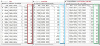
I attach the result of the accuracy measurement which is in the grid named "As is" of the first attached picture.
Measurements are scaled dividing by 2 from full scale (all -) to LSB (1 -).
The column Median contains the measured output voltage, the column Expected contains the expected output voltage of a 24 bit DAC with perfect accuracy, the column Difference contains the deviation between measured and expected voltage, the column Calibration contains the correction needed to get perfect accuracy expressed in number of LSBs, the column Error contain the percentage deviation between measured and expected voltage, the column Accuracy contains the actual precision of the DAC expressed in bits.
Although many have argued that sign magnitude architecture will improve the accuracy of the DAC the measurement confirms the theoretical culculation based on the resistors tolerance used in the R2R ladder network.
Using 0.01% and 0.02% resistors tolerance you get around 14 bit accuracy, more or less depends on the combination of the resistors error in the ladder.
This is confirmed by the THD measurement: 0.006% THD means -84dB which means 14 bit (14 * 6 = 84).
Just what has been said several times in this thread:
Reference DAC Module - Discrete R-2R Sign Magnitude 24 bit 384 Khz
Reference DAC Module - Discrete R-2R Sign Magnitude 24 bit 384 Khz
Then my DAM1021 is a 24 bit resolution DAC (28 bit if you consider the room for digital volume control) but it's also a 14-15 bit accuracy DAC.
When calibration is applied the accuracy improves as in the grid named "Calibrated" which contains the measurement after the correction was applied to each bit.
Unfortunately a fine correction is not applicable because of the issue I have mentioned above.
The accuracy improves up to 17-18 bit but not up to 22-23 bit as expected in the grid named "Expected fine calibration", which would need the measurement of the contribution of each resistor in the ladder to the output voltage.
I believe this would be possible if I found the way to get the DAC playing bit perfect, but I am not able to succed unless the designer will help.
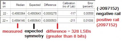
Finally I suspect there is something wrong in the math calculations inside the FPGA since the measurement indicates there is no symmetry between the positive and the negative rail of the magnitude architecture of the DAC.
I don't know if it depends on the filter I have used (I don't believe), but I have measured a wide difference between the positive and the negative rail when the same magnitude was applied to both rails.
The second picture shows the difference I have measured between the positive and the negative rail playing the same magnitude with opposite sign.
Since the magnitude is the same one expects perfect symmetry between the positive and the negative rails of the DAC, while I have measured at least 8 bits of difference.
Since I didn't expect such asymmetry I have checked each switch of the positive and negative when playing the same magnitude and to my surprise I noticed that the same bits are not turned on in both cases.
The switched on bits were different between positive and negative rail when the magnitude were the same.
This is very strange to me, maybe the designer could explain where I'm wrong.
Although I have not found the way to get my DAM1021 playing bit perfect I succeeded measuring its accuracy.
I have used the filter provided by koala887, volume is set to -99, potentiometer not installed.
I have sent DC samples to the DAC to measure the voltage at its output for each sample, from full scale (max output) to LSB, dividing by 2 every time.
I expected only one bit switched on for each DC sample but unfortunately it's not so.
I have cheked each bit with a DMM and the bits are not switched on as expected according to the 24 bit word I have sent to the DAC.
I don't know if the issue is related to the filter or to the digital volume processing, I have asked several times but unfortunately the designer did not help.
This issue does not affect the accuracy measurement because the DC samples are scaled dividing by 2, so every division one expects to get half voltage at the output:
- all bits on, 24 bit word max decimal value, expected max output voltage
- bit 23 on, 24 bit word is 4194304, expected full scale / 2 output voltage
- bit 22 on, 24 bit word is 2097152, expected full scale / 4 output voltage
- and so on until the LSB
Unfortunately this affects the calibration because to get a fine correction one would need to measure the contribution of each single bit (each resistor of the R2R ladder network) to the output voltage.
This means switching on one bit only (single resistor) each time to measure its own contribution.
Since I have not found the way to get the DAC playing transparent this was not possible and so the calibration is not perfect.
I attach the result of the accuracy measurement which is in the grid named "As is" of the first attached picture.
Measurements are scaled dividing by 2 from full scale (all -) to LSB (1 -).
The column Median contains the measured output voltage, the column Expected contains the expected output voltage of a 24 bit DAC with perfect accuracy, the column Difference contains the deviation between measured and expected voltage, the column Calibration contains the correction needed to get perfect accuracy expressed in number of LSBs, the column Error contain the percentage deviation between measured and expected voltage, the column Accuracy contains the actual precision of the DAC expressed in bits.
Although many have argued that sign magnitude architecture will improve the accuracy of the DAC the measurement confirms the theoretical culculation based on the resistors tolerance used in the R2R ladder network.
Using 0.01% and 0.02% resistors tolerance you get around 14 bit accuracy, more or less depends on the combination of the resistors error in the ladder.
This is confirmed by the THD measurement: 0.006% THD means -84dB which means 14 bit (14 * 6 = 84).
Just what has been said several times in this thread:
Reference DAC Module - Discrete R-2R Sign Magnitude 24 bit 384 Khz
Reference DAC Module - Discrete R-2R Sign Magnitude 24 bit 384 Khz
Then my DAM1021 is a 24 bit resolution DAC (28 bit if you consider the room for digital volume control) but it's also a 14-15 bit accuracy DAC.
When calibration is applied the accuracy improves as in the grid named "Calibrated" which contains the measurement after the correction was applied to each bit.
Unfortunately a fine correction is not applicable because of the issue I have mentioned above.
The accuracy improves up to 17-18 bit but not up to 22-23 bit as expected in the grid named "Expected fine calibration", which would need the measurement of the contribution of each resistor in the ladder to the output voltage.
I believe this would be possible if I found the way to get the DAC playing bit perfect, but I am not able to succed unless the designer will help.
Finally I suspect there is something wrong in the math calculations inside the FPGA since the measurement indicates there is no symmetry between the positive and the negative rail of the magnitude architecture of the DAC.
I don't know if it depends on the filter I have used (I don't believe), but I have measured a wide difference between the positive and the negative rail when the same magnitude was applied to both rails.
The second picture shows the difference I have measured between the positive and the negative rail playing the same magnitude with opposite sign.
Since the magnitude is the same one expects perfect symmetry between the positive and the negative rails of the DAC, while I have measured at least 8 bits of difference.
Since I didn't expect such asymmetry I have checked each switch of the positive and negative when playing the same magnitude and to my surprise I noticed that the same bits are not turned on in both cases.
The switched on bits were different between positive and negative rail when the magnitude were the same.
This is very strange to me, maybe the designer could explain where I'm wrong.
Attachments
- Home
- Vendor's Bazaar
- Reference DAC Module - Discrete R-2R Sign Magnitude 24 bit 384 KHz