The dam1021-12 rev7 is now in stock and ready for shipment. It will come with firmware with the updated PLL software. I will soon backport that PLL software to also support pre rev7 dam1021.
Sounds really nice! What was the update of the PLL now again and how has it affected the performance sound and measuring-wise?
Are you planning to also move the new PLL logic to the other products?
//
Wondering if I should upgrade from my rev1 ? 🙂 Still working great.
Unsure if the rev7 would fit into the audiozen board....
Unsure if the rev7 would fit into the audiozen board....
Sounds really nice! What was the update of the PLL now again and how has it affected the performance sound and measuring-wise?
Are you planning to also move the new PLL logic to the other products?
//
I second that. Soeren, could you please elaborate what you changed with regard to the PLL? Thanks!
Sounds really nice! What was the update of the PLL now again and how has it affected the performance sound and measuring-wise?
Are you planning to also move the new PLL logic to the other products?
//
The PLL have been refined a little, the oscillator is now controlled in steps of 1/16 hz, and updated only when needed. That matter mostly when multiple dams have to track each other. As I have said before, not something you can hear or measure audio wise.
It will be ported to other products as firmware get updated anyway.
After long testing on 2 different systems, one containing two 1121 and the other one 1024, my thinking is that +++ mode is more clean - particularly upwards. Haven't done it blind so it could be a "wish".
//
//
if anyone has a file with firmware and filters version 1.19, please share!
(dam1021 firmware and filters rev 1.19)
1021full_119.skr
(dam1021 firmware and filters rev 1.19)
1021full_119.skr
Here you go.
Why not use 1.21?
//
new firmware / new 4k filters completely broke my tonal balance in my DAC ... less bass and sibilance appeared. but I must say that my DAC has modifications and perhaps something did not work out correctly.
Here you go.
Thanks a lot!!!
DC samples issue
Hi Soeren,
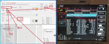
I'm trying to play some DC wave samples at different amplitude with my DAM1021 but I didn't succed.
The attached picture shows a DC wave sample 192kHz/24 bit where the MSB only is on (Big-endian 24 bit signed 4194304, hex 400000, binary 010000000000000000000000), please see the scope screenshot.
I expected to measure around 1 Vdc peak at the raw output of the DAC but I get noise only.
Is it due to the filter?
Is there a workaround to play the sample bit perfect?
Thank you
Andrea
Hi Soeren,
I'm trying to play some DC wave samples at different amplitude with my DAM1021 but I didn't succed.
The attached picture shows a DC wave sample 192kHz/24 bit where the MSB only is on (Big-endian 24 bit signed 4194304, hex 400000, binary 010000000000000000000000), please see the scope screenshot.
I expected to measure around 1 Vdc peak at the raw output of the DAC but I get noise only.
Is it due to the filter?
Is there a workaround to play the sample bit perfect?
Thank you
Andrea
Attachments
There is a high pass IIR filter used in all the stock filters.
Here is an edited version of a filter file with DC filter removed, you need a serial interface to upload it.
How to load custom filters for Soekris DACs | Super Best Audio Friends
I had to change extension to .txt to upload it here, it needs to be changed to .skr
Here is an edited version of a filter file with DC filter removed, you need a serial interface to upload it.
How to load custom filters for Soekris DACs | Super Best Audio Friends
I had to change extension to .txt to upload it here, it needs to be changed to .skr
Attachments
Last edited:
For something closer to 'bit perfect' you might want to use the 'NOS' filter instead to avoid any attenuation and keep the original sample values.
If you ask in filter brewing thread someone should be able to provide a filter file with the NOS filter and without DC filter.
If you ask in filter brewing thread someone should be able to provide a filter file with the NOS filter and without DC filter.
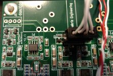
Is that an output coupling capacitor that is directly in the signal path? Or part of a low-pass output filter that connects signal to ground?
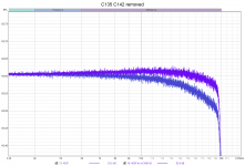
it's part of low-pass RC filter on ladder output.
as stated by Soren
C135 and C142 are 1500 pf NP0 ceramics, together with the 640 ohms impedance from the R-2R network they set the -3 dB 165 Khz point of the RC filter.
as stated by Soren
C135 and C142 are 1500 pf NP0 ceramics, together with the 640 ohms impedance from the R-2R network they set the -3 dB 165 Khz point of the RC filter.
Attachments
Last edited:
Thanks, that's what I thought. I had also seen some mention/complaints of output coupling caps, but couldn't actually work out where they might be in the circuit. So confirming these are just filters, and have seemingly very little influence, is reassuring.
(Also worth noting that on rev7 boards, the equivalent caps aren't labelled. But it seems obvious which caps they are, right between the two polymer caps on each channel.)
(Also worth noting that on rev7 boards, the equivalent caps aren't labelled. But it seems obvious which caps they are, right between the two polymer caps on each channel.)
Last edited:
- Home
- Vendor's Bazaar
- Reference DAC Module - Discrete R-2R Sign Magnitude 24 bit 384 KHz