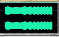
I generate a sinewave. At 11025 hz the DAM1021's amplitude is unstable and varies down to -3 dB peak (RMS is the same) from the target amplitude. This corresponds to the signal looking like a triangle at maximum and a clipped triangle (of lower amplitude but identical RMS value) at minimum.
The AD converters and the DAM1021 all use the same master clock. Other converters with and without sophisticated re-clocking hardware don't show this behaviour.
It has nothing to do with the AD converter or it being one the same clock as the DAM1021 or not. The DAM1021 does this on its own.
The AD converters and the DAM1021 all use the same master clock. Other converters with and without sophisticated re-clocking hardware don't show this behaviour.
It has nothing to do with the AD converter or it being one the same clock as the DAM1021 or not. The DAM1021 does this on its own.
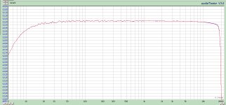
If you see a triangle on the output with a real scope it means the DAM output is not filtered (band-limited) enough to suppress harmonics of the digital audio samples above 20kHz.
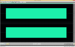
RMS is the same because the DAM1021 amplitude does not actually vary. I attached a screenshot of the first 50 seconds of your 11025.wav recording at 44100 Hz and HQ upsampled to 768000 Hz (this is a correct operation because of near-ideal ADC filtering). As you can see, the actual peaks have constant level.I generate a sinewave. At 11025 hz the DAM1021's amplitude is unstable and varies down to -3 dB peak (RMS is the same) from the target amplitude.
Soeren may describe it better than me but judging by what he said already DAM1021's DAC section is never locked to your master clock in any way, it always uses its own clock not derived from anything and constantly adjusted by 1 Hz according to FIFO fill.The AD converters and the DAM1021 all use the same master clock.
It is inavoidable if the reclocker uses an independent programmable oscillator. Such oscillator will almost always have small frequency difference with the incoming clock, less than its adjustment step.Other converters with and without sophisticated re-clocking hardware don't show this behaviour.
Attachments
I have Beyer Dynamic DT770 headphones, 250 ohm (worst case 200). DAM manual says >300 ohm. Will the phones work on the opamp output? Should I add a series resistor?
...
3) Output shift registers now running at 1.4M/1.5M sample rate, making FIR2 filter different. Will require new filter file, but plan to use same filter file for both old and new boards, firmware will load filters as needed.
@soekris
If I may ask, why?
I have Beyer Dynamic DT770 headphones, 250 ohm (worst case 200). DAM manual says >300 ohm. Will the phones work on the opamp output? Should I add a series resistor?
Should not be necessary to add a resistor, that may only increase noise and waste current. Those headphones should work fine.
I think it is intended to be read as "you can even drive >300Ω cans directly". The unbalanced out itself is 10Ω so that's fine.
@soekris
If I may ask, why?
Save a few bytes in a crowded FPGA?
Ok, I will try it directly. Though I must say you cannot waste current... 😉
I stand corrected 🙂 power!
Can anyone tell me who makes the ladder resistors used in the Soekris DAC and what their model name is?
Newer mid-range ladder DACs already use 0.005% precision resistors. I wonder if the lower precision resistors in the Soekris DAC are better in quality and will compete with competitors in this regard?
Newer mid-range ladder DACs already use 0.005% precision resistors. I wonder if the lower precision resistors in the Soekris DAC are better in quality and will compete with competitors in this regard?
Ok, I will try it directly. Though I must say you cannot waste current... 😉
In the meantime I soldered a headphone mini connector on the DAC. Works great, no complaints! 🙂
Judging by tweaks and improvements of this DAC, the resistors are certainly not its weak point. As a matter of fact, even 0.05% resistors give low enough THD certainly below threshold of hearing. 0.005% is just pointless overengineering to justify inflated price, IMO.Newer mid-range ladder DACs already use 0.005% precision resistors.
Newer mid-range ladder DACs already use 0.005% precision resistors. I wonder if the lower precision resistors in the Soekris DAC are better in quality and will compete with competitors in this regard?
You're missing one big point:
The Soekris DAC is a Sign Magnitude design, the distortion is relative to the signal level.
With a simple R2R DAC (Non Sign Magnitude), the distortion is relative to the full signal level.
So with a Sign Magnitude design you get much lower distortion also at lower levels.
You are confused between resolution and precision, the math is not an opinion (luckily)
Reference DAC Module - Discrete R-2R Sign Magnitude 24 bit 384 Khz
Reference DAC Module - Discrete R-2R Sign Magnitude 24 bit 384 Khz
No, I'm not confused, you don't grasp the concept of sign magnitide,
the Sign Magnitude is relative to the previous signal level sample, not to the full signal level.
the Sign Magnitude is relative to the previous signal level sample, not to the full signal level.
Please, read accurately:
"I explained this several times in this thread, with mathematical example:
do you agree that with 8192 (2 exp 13) step you can represent 13 bit?
if yes, you can calculate the ratio: 1/8192 = 0.000122
since resistor tolerance is given in percent, you can multiply 100 times:
0.000122 * 100 = 0.0122%
that's the resistors tolerance needed to reach 13 bit precision, or precisely a little more than 13 bit, but below 14 bit.
And again there is nothing correlated with the notation, since when the 14th bit will switch you loose half 1 bit of precision, on the 15th bit you loose 1 more bit and so on.
So you have a perfect 13 bit dac until the dynamic of the music is constricted within 13 bit.
Using 2 separate ladders for each channel (that's not the best practice, Burr Brown used a single ladder in their PCM63 and PCM1704), you can add 1 bit of precision, to reach 14 bit."
Now you are free to mathematically demonstrate the opposite.
- Home
- Vendor's Bazaar
- Reference DAC Module - Discrete R-2R Sign Magnitude 24 bit 384 KHz