Thank you!
This may be a silly question. When I set a dam to bal-left, or bal-right, I still get audio out of both channels, any idea why?
During my mock up of the dual mono build (using normunds boards) , I had a lot of noise on both channels, I figured I'd test them on their own, I don't get any noise, but I'm thinking that both channels outputting even tho they're set to only be L or R may have something to do with it.
Both channels are supposed to output, each "channel" is the differential signal; normal and inverted. How are you connecting them to your amplifier?
I was using the raw out put. I tried an XLR and RCA just for testing. I'm using a digital coax as the input
I couldn't find any info on the new Soekris 1541, it does look great(would get rid of the SMPSs right away of course 🙂 ) but is there the option to upload new filters as on the DIY boards?
I couldn't find any info on the new Soekris 1541, it does look great(would get rid of the SMPSs right away of course 🙂 ) but is there the option to upload new filters as on the DIY boards?
Those are not diy products, but there happens to be a serial connector, and it happens to use same firmware and same filter file....
And the switch mode power supplies are great, better than having a big heavy transformer with the line frequency noise and heat generating regulators....
In the dac1541 you first have LC filters after the switch mode power supplies, then there are six discrete low noise low impedance regulators.... But there also happens to be space for a connector for alternative powering....
Interesting tweak?
I'm using WaveIO card together with the dam1021. There is an isolator chip at the output of WaveIO card and an additional isolator chip at the input of the dam1021. At first glance this signal path seems not to be optimal, but there is really good reclocking on the dam side.
There should be a chance to isolate further:
The input side of the WaveIO isolator chip shares the same power supply with all WaveIO card components.
The output side of the DAM isolator shares the same power supply with the DAM card components.
And that's the tweak: Use a capacitor buffered battery for the remaining opposite sides of the two isolator chips. Both chips work fine with power supply between 3V and 5V. I'm using three LR6 batteries.
It works notably good in my system (faster bass, better resolution and detail) and it would be very interesting if anybody else will get similar results.
This hasn't been asked for a while (I searched and saw the other replies...), but I am having a problem updating my firmware.
Using Teraterm I can donload files allright, I have all the prompts but upon confirmation of the update I always get "incorrect image" after typing Y,
no matter what I do.
Tried several firmwares, no change... Any hints?
Thank you.
Using Teraterm I can donload files allright, I have all the prompts but upon confirmation of the update I always get "incorrect image" after typing Y,
no matter what I do.
Tried several firmwares, no change... Any hints?
Thank you.
Nevermind guys, figured it out.
All is good now.
I was going to say, that looked like a binary vs ASCII transfer issue...
Hi to all ,
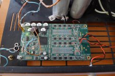
I think I need some help : today I tried the Vref mod by adding some MUSE 1000uF/50V at the points marked by soren in his post 3108 . The DAC works (in SPDif) , but every 20 seconds , it looses locking and at this time the 4V Vref disappears also . So I desoldered the caps and the problem still remain .
Any hints ??
Here is a picture of my implementation
Attachments
Understanding the I2S input
Hello
I have a AK4118 I2S converter, and want to use it's output for my DAM 1021 board.
The board is here:
https://world.taobao.com/item/41920458646.htm?fromSite=main
or
https://www.aliexpress.com/item/AK4...32556832083.html?spm=2114.40010208.4.7.eIWL7c
However, it describes the outputs as:
1 pin DSDON, 2 pin GND, 3pin DATA, 4 pin BCK, 5 pin MCLK, 6 pin LRCK
How does this map to BCLK IN | LRCK IN | DAT IN | MCLK OUT | FSEL IN please?
Finally, could anyone comment if there is an obvious 3.3v output from this board that I could use to power the DAM 1021 I2S vin?
Thank you sincerely everyone for any help - I am stumped and frustrated......
To connect to the DAM just use these pins:
Gnd ->Gnd
DATA -> DAT IN
BCK -> BCLK IN
LRCK -> LRCK IN
You can find 3.3V at several places on the board, like for example on the AMS1117 regulator. Just use your multimeter to make sure that you have found the correct voltage.
Gnd ->Gnd
DATA -> DAT IN
BCK -> BCLK IN
LRCK -> LRCK IN
You can find 3.3V at several places on the board, like for example on the AMS1117 regulator. Just use your multimeter to make sure that you have found the correct voltage.
Thanks for confirming Dimdim: so I don't need to provide an input to FSEL IN or use the DSDON out of the i2s board 🙂
Regarding the 3.3v: I thought I read somewhere that it was best to provide a separate 3.3v input to the DAM boards for i2s - shouldn't I be providing this from another source other than the DAM board itself?
Thanks again for your advice 🙂
Regarding the 3.3v: I thought I read somewhere that it was best to provide a separate 3.3v input to the DAM boards for i2s - shouldn't I be providing this from another source other than the DAM board itself?
Thanks again for your advice 🙂
OK - I just tested and found 3.3v at the bank of unused 5 pins on the board, however, it says in the 'blurb' from the seller "Note: the board did not write the 5-pin port (next to the button) what is not used, at the same time do not pick anything, the default can be empty! Unauthorized use of this 5-pin port lead to damage to the consequences of the board at their own risk!"
https://world.taobao.com/item/41920458646.htm?fromSite=main
Worth a go in your experience using this as the 3.3v source for the DAM anyhow or rigging up a 3.3v source myself?
Thank you 🙂
https://world.taobao.com/item/41920458646.htm?fromSite=main
Worth a go in your experience using this as the 3.3v source for the DAM anyhow or rigging up a 3.3v source myself?
Thank you 🙂
There's a chance that the 3.3V that you are measuring on this pin are not coming from a power supply pin but instead are a logic high coming from either the 4118 or the uC.
If I were you, I'd power down the board and do a continuity check between the 1117's output pin and the pin that you found. If it shows a short, you'll be OK.
If I were you, I'd power down the board and do a continuity check between the 1117's output pin and the pin that you found. If it shows a short, you'll be OK.
Success! The second pin in from the right is 0 resistance to the middle pin of the lm1117 🙂
Thanks for the advice, as, the end pin was also 3.3v but is registering at 10kOhm
Thank you Dimdim
Thanks for the advice, as, the end pin was also 3.3v but is registering at 10kOhm
Thank you Dimdim
Well: the sound is excellent - great separation and clarity.
I'm using the RAW outputs currently.
Bit thin and harsh top-end perhaps: could be a bit warmer, but, I'm hoping a tube buffer may help here: http://item.taobao.com/item.htm?id=40805026861
Being very much a 'noob' - there has been a lot of grinning going on by me since getting such a lovely sound out of this. I'd like to thank everyone in the forum for their help 🙂
I have seen quite a bit about power supplies: I'm using a regulated +-12v supply: http://item.taobao.com/item.htm?id=19445285988
What is the current view on using battery (say 2 x 10aa(a) NiMH packs) power?
Many thanks again forum: like most of you I am sure here on a DIY forum, I am extremely happy with my work but now want to improve it - hee hee.
- Home
- Vendor's Bazaar
- Reference DAC Module - Discrete R-2R Sign Magnitude 24 bit 384 KHz