US will of course have them too, EU just updated their website during the weekend and will also be a little faster shipping as they don't need to cross the atlantic first....
I'm working on the manual right now, will be up in a day or two.
will you review the price of dam1121?
smaller and reduced component count and the price same as dam1021
please review the price of oem line
thanks
will you review the price of dam1121?
smaller and reduced component count and the price same as dam1021
please review the price of oem line
thanks
I really have no intend to discuss my pricing here, but considering the still relatively low volume and my time spend on firmware, I believe the pricing is very very good.... The boards do have different quantities of high precision resistors, the most expensive parts....
I you want better pricing, order OEM volume 🙂
Sorry Soren
can you provide more detial of dam1121 before we order
I want to get all pin out and how many power supply I can supply to the dam1121
thanks
how about powering the dac with 12V batteries? Instead of modding all these things isnt it better to first cutoff the noise from the source itself?
I really have no intend to discuss my pricing here, but considering the still relatively low volume and my time spend on firmware, I believe the pricing is very very good.... The boards do have different quantities of high precision resistors, the most expensive parts....
I you want better pricing, order OEM volume 🙂
I thought the oem board would be a cut down version of 1021. In this case you would just recycle the (main part) firmware and the main design.
I also find the price too steep especially for a new product with new FW. Knowing the history of 1021 development I hope the oem version will not have too many bugs.
I would encourage you to consider a special (call it introductory) price for existing customers. Perhaps we can organise a group purchase to help you boost the short-term sales.
Otherwise, same as dimdim, I will pass for now and continue modding my 1021.
Last edited:
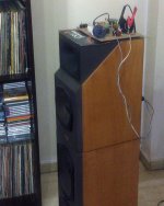
Its I wanted to listen with possible future systems my freshly revised speakers before calling the crossover design done and screwed back in the cabinets guts. The local DAC guys enthusiastically responded and soon a parade of hardware and streamer jargon happened in the house. Many thanks.
Could you please shed some light on the upgrade of your speakers. I guess the main part that has been upgraded is the crossover.
Could you please shed some light on the upgrade of your speakers. I guess the main part that has been upgraded is the crossover.
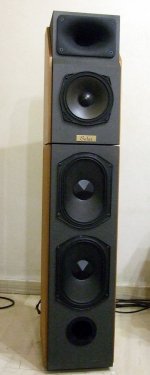
Its a diy self designed speaker that I have. I changed the HF part from tweeter to compression driver & horn. So the top cabinet had to be hacked for refit and the crossover had to be redesigned as a whole. Parts are plain vanilla from the bin and the connectivity is ironic before final fit. Crocodile clips are feeding power to the crossovers through thin old wires no better than lamp chords. 😀
Attachments
From the comments I was thinking that SOEKRIS was asking more for the OEM board and after looking I see that is not the case.
The parts not included are not expensive parts. Not as if their removal would make much of a dent in the parts cost. No question the resistors are the expensive parts of the board and then the FPGA chip. The rest is pocket change ...
Look at it this way: if you are going to modify your board extensively the time saved makes the board much less expensive if you value your time.
Can't decide if I could put myself through the process again. My DAC sounds so good at this point, in conjunction with the SDTrans, I am satisfied beyond belief.
I am tempted, though ...
Its a diy self designed speaker that I have. I changed the HF part from tweeter to compression driver & horn. So the top cabinet had to be hacked for refit and the crossover had to be redesigned as a whole. Parts are plain vanilla from the bin and the connectivity is ironic before final fit. Crocodile clips are feeding power to the crossovers through thin old wires no better than lamp chords. 😀
How do you like compression driver & horn compared to the tweeter HF part?
How do you like compression driver & horn compared to the tweeter HF part?
I want to listen at four to five metres away from the speakers in a non treated room so horn directivity control wins any direct source hands down. 🙂
I want to listen at four to five metres away from the speakers in a non treated room so horn directivity control wins any direct source hands down. 🙂
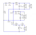
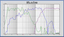
Interesting. What order crossover are you using in your new design, from the picture it looks like the 3rd order. And what are the crossover frequencies?
BTW I have seen this cheap gadget. Maybe a nice partner for my old SPDIF DACs. So to can listen to them with newer music files meanwhile through Foobar on an old battered C2duo laptop I summoned from the crypt. Does anybody have it and is it workable?
An externally hosted image should be here but it was not working when we last tested it.
Interesting. What order crossover are you using in your new design, from the picture it looks like the 3rd order. And what are the crossover frequencies?
Here are the details you asked for
Attachments
Question, Søren,
I like to know if there is a way to make the Soekris Dac capable to play MQA files?
I think it is in the firmware where the solution lies.
Is there a way to do that?
Now that also Warner is on the list for the MQA.
MQA | Our partners,
I think it is a way for streaming the music from Tidal and Qobuz.
The market usually determines price. If not many sell at the price, maybe it will be lowered, but if the demand is there, then maybe not.
Also, IMHO, this DAC is a bargain at the price paid.
Also, IMHO, this DAC is a bargain at the price paid.
Question, Søren,
I like to know if there is a way to make the Soekris Dac capable to play MQA files?
I think it is in the firmware where the solution lies.
Is there a way to do that?
Now that also Warner is on the list for the MQA.
MQA | Our partners,
I think it is a way for streaming the music from Tidal and Qobuz.
Seems just a new compression algorithm, don't really have anything to do with the DAC....
BTW I have seen this cheap gadget. Maybe a nice partner for my old SPDIF DACs. So to can listen to them with newer music files meanwhile through Foobar on an old battered C2duo laptop I summoned from the crypt. Does anybody have it and is it workable?

This ones gathering quite the following
With one of the new xmos chips
m.ebay.com/itm/F-1-XMOS-USB-Digital-Interface-Module-XU208-U8-upgraded-version-/111961717820?hash=item1a11703c3c:g:UI0AAOSwAvJXBdC1
Ive the new usb to i2s from diyinhk and i think theres something to these new chips
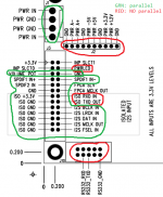
Yes, extra long pin headers are the trick. Attach them to the top board, so you have equal lengths on top and bottom which you can then plug into the board below. Parallel the I2S, SPDIF, ISO 3.3V, ISO GND, GND's and volume pins. (yes paralleling the volume is fine)
Don't parallel any of the others like the +3.3V or isolated serial ports. Use only the top board's +3.3V/1.8V to power your SPDIF toslink and Coaxial SPDIF biasing.
Thank you spikestabber, very helpful!
I created the attached diagram, which I think is right, though still a few questions:
You said, "Don't parallel any of the others like the +3.3V" - which +3.3V are you talking about? The upper-left of J3 +3.3V is part of the volume control, which you said is OK to parallel...
Also, not sure about "INP SLCT1", "INP SLCT0", "FPGA SLV", and "FPGA MCLK OUT" pins of J3.
Thanks again!
Attachments
Thank you spikestabber, very helpful!
I created the attached diagram, which I think is right, though still a few questions:
You said, "Don't parallel any of the others like the +3.3V" - which +3.3V are you talking about? The upper-left of J3 +3.3V is part of the volume control, which you said is OK to parallel...
Also, not sure about "INP SLCT1", "INP SLCT0", "FPGA SLV", and "FPGA MCLK OUT" pins of J3.
Thanks again!
The upper 3.3V is +3.3V proper, not part of the volume control per se. The volume control is the input pin that takes 0 to 3.3V and interprets that as -99 to +10 volume.
Don't parallel the +3.3V pin period. You will however use this pin on the top board only to power SPDIF toslink and one side of the volume pot.
Parallel the input select pins if you are using them.
MCLK and SLV I left floating as Soren hasn't implemented slave clock input.
I don't have any external controls on my setup as everything is controlled by dam1021.py that tees to both serial ports for specific commands, such as input, volume, etc.
Last edited:
The upper 3.3V is +3.3V proper, not part of the volume control per se. The volume control is the input pin that takes 0 to 3.3V and interprets that as -99 to +10 volume.
Don't parallel the +3.3V pin period. You will however use this pin on the top board only to power SPDIF toslink and one side of the volume pot.
Parallel the input select pins if you are using them.
MCLK and SLV I left floating as Soren hasn't implemented slave clock input.
I don't have any external controls on my setup as everything is controlled by dam1021.py that tees to both serial ports for specific commands, such as input, volume, etc.
I think I got it... Part of the confusion is that there are two +3.3V headers: one in J3 (i.e. the big 2x13), and also one in J2 (1x10). (I'm guessing those are probably paralleled at the board level?)
Either way, glt's blog shows using the J2 +3.3V header for powering TOSLINK, and the J3 +3.3V header for one leg of the volume control potentiometer. But I assume you could swap which +3.3V you use for volume pot or toslink power.
So what I'm thinking is this: neither +3.3V header gets paralleled. (It would probably damage one or both boards to parallel any of power headers, right?)
From the "top" board, I'll use one +3.3V to power toslink (probably from J2 as suggested by glt's blog).
And also on the "top" board, I'll use the other +3.3V (J3) to go to one leg of the volume pot. The other two legs of the volume pot will go to VOLUME_POT and GND headers in J3; those two headers will be paralleled to the "bottom" board.
Bottom board's +3.3V (and all power headers, for that matter) are left open.
Thanks again, obviously I'm in need of some hand-holding. 😱
- Home
- Vendor's Bazaar
- Reference DAC Module - Discrete R-2R Sign Magnitude 24 bit 384 KHz