Isn't those caps you marked connected to ground by the vias you see on the other side? If so, they cant be in series...
//
//
You can easily check with a multimeter if a side of the caps connect to ground.
They're not there anymore on the R7 version, instead the R7 has a reclocker after the FPGA.
They're not there anymore on the R7 version, instead the R7 has a reclocker after the FPGA.
But to my surprise there are no stock of dam1021s now. No reply from soren as well. Did anyone tried to contact him?
Nice inputs to understand what is actually happening. But what is the role of these capacitors? They look like in series with the signal?
That is the rev 1, and that image is no longer relevant. But, I would guess those caps are local uncoupling for the switch registers, and they will not be part of the audio signal.
In terms of availability, I do know Soekris was having quite a lot of difficulty sourcing parts, particularly the FPGA at the heart of the DAC. If there is no stock right now, I suspect you might be waiting a long time.
Thermometer bits? never heard of that and what is the use of it?Maybe I should tell that it's actually what's called a segmented DAC, it consists of the 1 bit sign, a 2 bit unit element (also called thermometer) section for the two MSB bits, and a 25 bit R-2R section for the rest, totally 28 bits.

When it comes to the ripple on the shift registers is the ripple of 400uV I think is quite high? Then what is the output noise from the +/- vref? less than 100micro volts? did anyone measure it?I understand, but based on the information we have it appears that the LVC595 can contribute 800uV of ripple, and rev2 stock vref 400+uV based on Paul's simulation. I understand that in rev.3+ you added 300uF per rail, but we have no data on how that will affect the system. Paul's further simulations are mostly based on his low-res mod. He justified the mod by showing a simulation of bambadoo's 4000uF + factory mod config which resulted in 408uV ripple at 100Hz. When low-res mod (0.01R) is added, it drops to 48uV which is very consistent with the ripple at higher frequencies. Like I mentioned last night, the LSB of a 4V 16bit ladder is 61uV. I hope these appear to be valid theoretical reasons to worry about stock performance even on later revisions. Empirically, we have at least three reports of significantly improved sound quality when more vref capacitance is added. So perhaps there is slightly more to be said if the goal is to get the system to sound as good as it reasonably can, and no one is suggesting batteries everywhere. There is plenty of reason to believe that some well-calculated and relatively simple mods can result in significant SQ improvements. This does not have to mean that the latest versions do not sound great.
We don't expect to understand the full circuitry and we certainly respect your time. I believe that most parts of the system are designed to near perfection which makes possible the great results that everyone is getting despite several inherent technological limitations in the system. But based on the theoretical and empirical evidence of the improvements to be gained in the vref circuit even in the newer versions, I cannot help but believe that there is some significant improvements to be had with simple mods (caps and an SMD resistor perhaps), both theoretical and sound-wise. All of this is a request from the user community for you to help point us in the right direction since you are the only person with the technical expertise and system knowledge to do so. If it were only a problem of capacitance, trial and error would be the best way to go, but things appear to be more complicated here to require the predictive power of simulations. Again, this is us asking for help...
Here's Paul's simulation result again for your reference: Vref musings: the final frontier? | moreDAMfilters This post-dates hifidurino's comprehensive review on the vref mods, and vref discussions here ended around page 350 (Sep. 15).
Reclocker after FPGA in v7? where is it? I see only Vrefs on the left hand side of the ladders but where is re-clocker in here?You can easily check with a multimeter if a side of the caps connect to ground.
They're not there anymore on the R7 version, instead the R7 has a reclocker after the FPGA.
Attachments
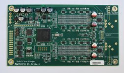
In rev7 the clock is driving the shift registers directly through flipflops (reclocker) U46 and U47,
in previous versions the clock went through the FPGA and then to the shift registers.
See this post from Soekris with all rev7 mods.
in previous versions the clock went through the FPGA and then to the shift registers.
See this post from Soekris with all rev7 mods.

The dam1021 is not eol, but things are going slow here right now.... I was working on a dam2021 with Lattice FPGA, but have now changed my mind on that, as the Xilinx FPGA's are now much easier to get at a reasonable cost... I will probable get dam1021-12 rev 7 stock around year end....
I’d like to add my vote to TNT’s for 1121 production, please.typing error, no schedule for dam1121....
- Home
- Vendor's Bazaar
- Reference DAC Module - Discrete R-2R Sign Magnitude 24 bit 384 KHz