Have no clicks and pops with my dam1021 even with firmware 1.19. It is rev1 with all necessary mods. Using it with a rpi.
However another dac that I have had these issues. Yes it was part of a firmware/driver issue but only with windows. When I used a linux distro all clicks and pops were gone.
Not sure why it was so..
That's interesting. I just switched from WASAPI push to event. Maybe that would help a bit. It appears to me that 1.06 has less crackling/clicks/pops than 1.19. But there's too much potential variance in my observation given how infrequent the clicks are. Will report back later. I guess Soren doesn't believe that there's a bug in v1.19 hence the lack of response which isn't unreasonable...
The dam is part of a preamp.The Kuartlotron is following a relais based volume control, with 10k input impedance, in this application it sounds better to me than no impedance converter after the volume control. Generally the Kuartlotron seems to have very little coloration, it is a simple and great buffer...
But I ran the dam for years straight into an amp with 22k input impedance and used just the raw outputs, sounded great. (Maybe even better than today, but I changed a few variables in my stereo setup in the meantime, so it is hard to say).
So I can't really help. Sorry.
By the way. I just removed the coupling caps and music sounds even better, even with that tiny little voltage offset....
Thanks for the response. Yes, I agree the Kuartlotron is good. But so are those raw outputs....🙂
FWIW I have no issue with clicks or pops in the single-ended 1121, a balanced 1121 and several 1021 builds for others - all running 1.19. Again FWIW, they run various inputs, RPIs, USB, SPDIF. None are fed from a PC.
FWIW I have no issue with clicks or pops in the single-ended 1121, a balanced 1121 and several 1021 builds for others - all running 1.19. Again FWIW, they run various inputs, RPIs, USB, SPDIF. None are fed from a PC.
Using WASAPI event went well for a few hours with 1.06 so I upgraded to 1.19 again. Had a click a couple of minutes in... I wouldn't be surprised if my build is at fault - anything that I should look out for?
I'm calling it... 1.19 has more clicks than 1.06 (which might have none using proper WASAPI event mode). I believe I've had clicks with iPhone too.
Btw, does XMOS still have an advantage over Amanero in dam1021?... Or are they equally well-suited?
Btw, does XMOS still have an advantage over Amanero in dam1021?... Or are they equally well-suited?
Last edited:
Would be waste of time and just add complications. No music have 28 bit content, only real use is for volume control, and my 28 bits are mostly for the bragging rights anyway....
Actually the errors in the R-2R network is more or less random.... But I have been thinking about linearity correction, more in the line of having a slow but very precise ADC measure the DAC during manufacturing test and save a correction table in memory for xx MSB bits.
I actually have space for those parts on my test jig PCB, and it would be easy to implement in the FPGA. But on the other hand it's a question of diminishing returns, it would add significant test time, I doubt that you could hear any difference....
But when I get time I will see how good it could get, at least it might be usefull if I want to use the R-2R DAC in test equipment....
It's kinda interesting how precise and fast a monolithic SAR ADC can be, but not a monolithic non delta sigma DAC....
Did anything come out of this?... Sounds super interesting!
On multiple DAC's, still working on that, kinda have two options, will implement both so we can figure out what works best in the different scenarios:
Sync before reclocking FIFO, no jitter and the clock control circuit will keep them synced to around one bit rate clock pulse, which at 44.1 Ksps is .35 uS. Speed of sound is around 0.1 mm in 0.35 uS.
Sync after reclocking FIFO, a tiny bit of jitter added due to clock wiring, but synced to 0 uS. Especially if you use the first master DAC for the highest audio frequencies I doubt there would be any audible effects.
Does this have to do with how dual-mono works now in dam1021?...
I have a problem not with pops or clics but with random crackling noise. In some situations it can take hours for it to emerge, in other situations it comes every minute and lasts for some seconds. The sound reminds me of a tube amplifier I had with an electrolytic capacitor that was faulty.
It is mostly in one of the channels (right), and rarely when it is the most noisy with a smaller hint in the left channel.
A description of my system and what I have tried might be helpful for diagnosing:
I have a MiniDSP Nanosharc I use as crossover, followed by two DAM 1021, and then two amplifiers fed from the raw output. The DAM 1021's are both powered by one DIYINHK regulator from a transformer with 8V. They have the same software ( the newest). This setup made it easy to shift between the two DAM's both in input and output, which made me sure that the fault is to be found in the one DAC - the other performs flawlessly. What is surprising for me is that if I cut the signal ( shot down the MiniDSP) the noise disappears, and it might last minutes or more before it comes again.
Where should I look? Am I right in suspecting a leaky capacitor on the board? Can it be in the power regulation on the DAM, if it mostly is in one channel?
Any suggestions from those of you who know much more about the construction of the DAM 1021.
Did you try PM Soren? Sounds like a serious problem.
I have some new dam1021 firmware for testing, it hopefully should fix the issue some are seeing with small "clicks" on rev 1.19, I can't be certain as only some have issues and my prototypes here don't....
For now it's just the fpga firmware for testing, just down and install as normal, firmware 1.19 must already be loaded, if not install firmware 1.19 first.
http://soekris.dk/download/dam1021/1021fpga_120.skr
Please let me know how it goes asap.
Sorry must've missed this. Just updated and testing now
Last edited:
So far so good. I have a feeling 1.20 FPGA did it. Will post back if anything else happens. Thanks Soren!
To connect to the DAM just use these pins:
Gnd ->Gnd
DATA -> DAT IN
BCK -> BCLK IN
LRCK -> LRCK IN
You can find 3.3V at several places on the board, like for example on the AMS1117 regulator. Just use your multimeter to make sure that you have found the correct voltage.
I just realized my problems may be entirely due to the fact that I left Ground on Amanero hanging. If I have 3.3V and ISO GND already connected to an external power source, can I just attach Amanero's GND to the ISO GND?.. Shorting the two seems to remove locking problems produced in special conditions....Thanks
Connected the GND on Amanero and the problem seems to have gone away. Updated to 1.19 and will post if I hear the clicks again. Sorry for the confusion... In case it's of use to anyone, the isolated side of the dam now shares the ground of Amanero/USB input and disconnected from chassis ground and signal ground. The symptoms were actually really serious - using iPhone as USB input causes severe lock issues on the bottom board (the one closer to Amanero) if Amanero is positioned in certain ways, quite bizarre I know. PC seems to work okay except for the occasional clicks (not sure if I got rid of it completely though, fingers crossed...), probably just luck that the PC ground is close to the floating ground of the PSU for the isolated side. I managed to overlook it since last year because issues with my phone kind of disappears when Amanero is laid flat above the chassis. Anyways, I'm really glad I got over this noob mistake 😀
Last edited:
Did anything come out of this?... Sounds super interesting!
Does this have to do with how dual-mono works now in dam1021?...
Quick bump. The DAC already sounds great as is and perhaps less distortion wouldn't really matter subjectively. But if it's possible to "calibrate" the resistors and shift registers somehow, perhaps without measuring each component by hand which would be cost-ineffective and primitive, it would appear to be a solid step forward in R2R manufacturing technology. The compensation techniques in Holo Spring seem interesting. The full technical details appear to be unpublished but it would seem that software calibration can achieve the same if not better effects, perhaps with some very small quantization error? Still sound super interesting to me nonetheless.
P.S. If this doesn't violate any existing patent....
But I now worry that Soren being the practical type won't see it as worthwhile... It is quite interesting that a lot of Soren's decisions are probably not found anywhere else in the "hifi industry", e.g. using SMPS, "skimping" on vref caps, using slightly lower precision resistor in LSB, etc. Rather refreshing when many competitors base their advertising campaigns on excessively perfectionistic technical details that probably help little towards an accurate judgement of the actual equipment performance.
But I now worry that Soren being the practical type won't see it as worthwhile... It is quite interesting that a lot of Soren's decisions are probably not found anywhere else in the "hifi industry", e.g. using SMPS, "skimping" on vref caps, using slightly lower precision resistor in LSB, etc. Rather refreshing when many competitors base their advertising campaigns on excessively perfectionistic technical details that probably help little towards an accurate judgement of the actual equipment performance.
Last edited:
Somewhere in the dark depths of this thread I once suggested to correct, to some extent, the nonlinearity of the DAM, due to the resistor tolerances, by software in the FPGA. There was mostly skepticism if that could work.
I now got my hands on some chinese 6.5 digit multimeter and so had the opportunity to some basic tests myself.
I measured the output voltage, with only one bit set, for the most significant bits. Then I used the lower bits to correct the errors.
Here some measurements for a 997 kHz signal.
First at -1dB: First picture uncorrected, second corrected, third overlay.
View attachment 553643 View attachment 553644 View attachment 553645
Second at -6dB: First picture uncorrected, second corrected, third overlay.
View attachment 553646 View attachment 553647 View attachment 553648
One sees only a slight improvement of the THD, but looking at the harmonics in detail, reveals that the low order harmonics are improved, whereas the higher get slightly worse.
I hat to modify the input signal and bypass the DAM filters for the test, as the correction does not commute with the filters. The right place would be to correct it in the FPGA after the filters. But only Soeren could provide that feature. I think it looks promising enough to be considered as an option in some future FPGA firmware.
There is a lot room for improvement: in the measurement procedure, the measurement equipment, .... I think the correction could be pushed much further. But as long as the firmware does not support it, I think it is not worth to put more energy in the research.
Hmmm, missed this...
Quick bump. The DAC already sounds great as is and perhaps less distortion wouldn't really matter subjectively. But if it's possible to "calibrate" the resistors and shift registers somehow, perhaps without measuring each component by hand which would be cost-ineffective and primitive, it would appear to be a solid step forward in R2R manufacturing technology. The compensation techniques in Holo Spring seem interesting. The full technical details appear to be unpublished but it would seem that software calibration can achieve the same if not better effects, perhaps with some very small quantization error? Still sound super interesting to me nonetheless.
I have considered that, actually have space for the circuit needed for calibration on the board I use for testing the dam1021....
But with the low distortion I'm already getting, I don't consider it worthwhile doing calibration, you just don't have to compensate for absolute precision, you also have to compensate for aging and temperature drift....
Also, a Sign Magnitude DAC are so much more precise at lower levels that it don't need any compensation....
So it would be like calibrating a monitor? Not a one-time thing but need to recalibrate frequently to maintain precision?... It might still be worthwhile if the aging and temp drift are well-matched across resistors, or at least much better matched than the absolute error of the resistors? I don't know enough about resistor manufacturing but maybe the temperature coefficient is more of a constant than a range that reflects the material and construction whereas tolerance is more of an error (that can be corrected)?
Also, a quick noob question... I just realized that I might've thought the "left channel" (viewed from the FPGA towards the ladder) was + in dual-mono operation, but I might've made an error last year when I wired everything together (and your faulty drawing didn't help..😱). Can you confirm if the "left channel" (which is probably right channel in normal operation) is + or - polarity in dual-mono? Thanks a bunch!
Right channel is + in balanced mode, Left is -
Right channel is + in balanced mode, Left is -
Yes! No need to rework the wires 😀 Although you provided us with polarity inversion functionality so I was probably okay either way. Thanks!
Have you considered my comment on calibration yet? What do you think about Holo Spring's approach? 😱
Edit: The right/left polarity makes perfect sense - right is often red which would be + polarity in this case. Not that the +/- and left/right distinction can ever hold at the same time, but it would make possible a coloring scheme on the RCA jacks that works for both modes. Great!
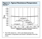
Edit2: I take back my comment on TCR. It is indeed defined as the upper bound of a range, not a constant that reflects the exact characteristic of the individual unit...
Edit3: This Vishay FRSM series graph seems to suggest that there is perhaps more consistency in thermal drift than variances?
Attachments
Last edited:
Yes! No need to rework the wires 😀 Although you provided us with polarity inversion functionality so I was probably okay either way. Thanks!
Have you considered my comment on calibration yet? What do you think about Holo Spring's approach? 😱
afaik, Holo is not Sign Magnitude, so they need to do something to get good results at low levels. Just like Schiit Audio use those very precise Analog Devices industrial DAC chips.
My DACs and DAMs are all Sign Magnitude and are level exact down to the noise limits.
Some don't know or understand the Sign Magnitude principle, so please read up on it and understand it before commenting.
Edit3: This Vishay FRSM series graph seems to suggest that there is perhaps more consistency in thermal drift than variances?
Vishay makes some very good resistors. But note that for most resistors, the temperature coefficient is worst at the temperature limits, not the temperature that a Audio DAC works at. And the resistors usually track each other.
afaik, Holo is not Sign Magnitude, so they need to do something to get good results at low levels. Just like Schiit Audio use those very precise Analog Devices industrial DAC chips.
My DACs and DAMs are all Sign Magnitude and are level exact down to the noise limits.
Some don't know or understand the Sign Magnitude principle, so please read up on it and understand it before commenting.
That's fair. But why aren't they using sign magnitude?... (and they did get pretty impressive, even if more or less useless, THD+N stats)
Vishay makes some very good resistors. But note that for most resistors, the temperature coefficient is worst at the temperature limits, not the temperature that a Audio DAC works at. And the resistors usually track each other.
Not sure what you mean. It seems 25C is best for TCR which should be close to the operating temp of the resistor ladders making it more advantageous for dam1021. My point was more about the potential relative consistency (higher tracking precision than the TCR specified?) among resistors and how that would not cause problems for a device calibrated at room temp. Maybe I was wrong...
Last edited:
- Home
- Vendor's Bazaar
- Reference DAC Module - Discrete R-2R Sign Magnitude 24 bit 384 KHz