these the parts in question?

Could you please publish some close up pictures of the modified areas.
Does anyone know if the clock is affected by the heat from the 3.3V LDO nearby? This regulator has been running well above 60-70C just by feeding 15VDC into the board. I wasn't sure if it was brought up before so I am asking because a while back I removed the LDO's on both of my boards and now feed them by Sparko 3.3V regulators offboard. There may be a noticeable improvement, I believe there is but its all subjective. The clock area is very cool now.
May I ask for a recommendation, please? I'm putting together a two board, dual mono DAC. What size transformers should I be looking for? What's the max current draw of the Board? Thanks!
spikestabber,
I would bet the clocks would rather be warm than cold.
Cold is relative to what they were before, they do generate their own heat. Warm is more accurate, rather than very warm/hot.
Hi,
Can anyone confirm that FSEL IN works (switches MLCK OUT between 45 and 49 Mhz)? I did RPi+dam1021 working and now I want to try BBB with dam1021 and will be nice to use MLCK from dam1021 to drive BBB in slave mode. I found information in other thread:
http://www.diyaudio.com/forums/group-buys/227502-amanero-isolator-reclocker-gb-210.html#post4265557
but is not clear to me how it could work because in attached picture is no FSEL IN - BBB connection.
Cold is relative to what they were before, they do generate their own heat. Warm is more accurate, rather than very warm/hot.
Well, that is profound.
I think you will find the clocks prefer a warmer environment than what they can produce all by themselves. Either by proximity to other heat producing devices or by some kind of enclosure.
Which is what I would have thought you would have deduced.
Well, that is profound.
I think you will find the clocks prefer a warmer environment than what they can produce all by themselves. Either by proximity to other heat producing devices or by some kind of enclosure.
Which is what I would have thought you would have deduced.
Chassis gets quite warm with all the shunt/linear regulation in there, I think the clocks are in good company, just not adjacent to a component running in excess of 70C.
After reading this thread in its entirety, this was brought up a few posts back;
What the reason for this exactly? a provision for DSD? If I read right, all the filters are at the users control so no further processing is actually done on that Mhz data after it enters 384 stage.
This doubt coincides another of mine regarding DEM scheme in the older multibits (yes, R2R is different but) in the TDA I there's an internal oscilator - for DEM.
I never quite figured how it works, or how the once oversampled 352khz data relates to it but it does also run at MHz also) but I don't think this feature of DAM is related, unless it is? Anyone care to enlighten? I know it was a sawtooth so I figure its related to the shift register or something.
Regarding the +10db issue a few posts back. I agree a level meter would be a nice touch to consider. The best 'old school' commercial PCM offerings have had horizontal meters on the front, they are appealing and much to be associated with 'the profession', i.e. lavry engineering and even maybe pacific microsonics (I realise they are ADs same thing). More segments could further associate with 'uber precision' - people would jump at that because it's little details that count!
Anyway, despite 2 days to read through the thread, one amusing element in the early stages was when DAM prototypes were being tweaked and in some cases even destroyed. IF it were me i'd of taken all those photographs of my masterpiece with added extra impurites as a huge f&$* you to the face, -
"Hey I know you took you a while to plan this out soren but here, GIANT CAPS HERE PLOP, snap, upload, POST, "LOOK". Incredibly funny I think..
Perfected and immediately marred with.
Like presenting fine danish cuisine to a .... [enter punchline]
The developments did prompt the vref correction, so not all bad I guess. Still funny.
Keep up the good work, I wouldn't mind one myself but I'd need to save up for a while. 🙄 (Not that the price point is bad!)
dam1021 will always have the 2.822M/3.072M final sample rate, but t.ex. repeating the same 44.1K samples 64 times is like no oversampling....'
What the reason for this exactly? a provision for DSD? If I read right, all the filters are at the users control so no further processing is actually done on that Mhz data after it enters 384 stage.
This doubt coincides another of mine regarding DEM scheme in the older multibits (yes, R2R is different but) in the TDA I there's an internal oscilator - for DEM.
I never quite figured how it works, or how the once oversampled 352khz data relates to it but it does also run at MHz also) but I don't think this feature of DAM is related, unless it is? Anyone care to enlighten? I know it was a sawtooth so I figure its related to the shift register or something.
Regarding the +10db issue a few posts back. I agree a level meter would be a nice touch to consider. The best 'old school' commercial PCM offerings have had horizontal meters on the front, they are appealing and much to be associated with 'the profession', i.e. lavry engineering and even maybe pacific microsonics (I realise they are ADs same thing). More segments could further associate with 'uber precision' - people would jump at that because it's little details that count!
Anyway, despite 2 days to read through the thread, one amusing element in the early stages was when DAM prototypes were being tweaked and in some cases even destroyed. IF it were me i'd of taken all those photographs of my masterpiece with added extra impurites as a huge f&$* you to the face, -
"Hey I know you took you a while to plan this out soren but here, GIANT CAPS HERE PLOP, snap, upload, POST, "LOOK". Incredibly funny I think..
Perfected and immediately marred with.
Like presenting fine danish cuisine to a .... [enter punchline]
The developments did prompt the vref correction, so not all bad I guess. Still funny.
Keep up the good work, I wouldn't mind one myself but I'd need to save up for a while. 🙄 (Not that the price point is bad!)
Well,
If you have never destroyed anything in DIY audio only one assumption can be made: you have never done anything.
The destroyed boards led to a good end and implementation but whatever you do DO NOT do anything to your board. It is not recommended. That is if you are ever able to save up enough to buy one.
Reading a thread through even though you cannot afford the modest cost of the board and then making inane comments abut a process of which you have no understanding. Wish that was more rare ....
Well,
If you have never destroyed anything in DIY audio only one assumption can be made: you have never done anything.
Now there's a statement worthy of a signature line! Maybe you should add it to your signature, Rick.
Still smiling....
I have never destroyed a DAM board but I have destroyed other things.
I neither have a signature line not intend to start one. They are usually even more annoying than destroying something while DIYing.
I am squarely a mid-level hobbyist not unlike the truly heroic folks who do the real work in hobbyist audio. Nonetheless, I have had my share of mishaps.
But when that fellow made his remark squarely aimed at nige2000 I got riled.
Due to nige's determination I have an exceptionally fine sounding DAC since I have followed his advice for this DAC. Sure it sounded pretty good to begin with with just transformers attached but with the full on battery mod the thing is truly fine.
I hope that fellow's conception of good food is more informed than his assumptions about audio gear. Not that I have ever heard anyone go on and on about Danish cooking - I do not care about food so I would not know the merits. I just want the stuff to keep me alive, My feelings about food are similar to the majority of folks concern for good audio! One has to make choices!
Here is a schematic to show how to connect the SPDIF inputs. Please note that the FPGA LVDS Receiver need to be biased around 1.25V, convenient there is 1.2V available from the FPGA Core voltage at J2.
(First drawing had incorrect pin numbers on the toslink receiver)
Did anybody use this or other schematic to feed dam1021 through
SPDIF inputs? I do not want to use a transformer, if possible.
I tried it with firmware 0.99 and it didn´t work.Hi,
Can anyone confirm that FSEL IN works (switches MLCK OUT between 45 and 49 Mhz)? I did RPi+dam1021 working and now I want to try BBB with dam1021 and will be nice to use MLCK from dam1021 to drive BBB in slave mode. I found information in other thread:
http://www.diyaudio.com/forums/group-buys/227502-amanero-isolator-reclocker-gb-210.html#post4265557
but is not clear to me how it could work because in attached picture is no FSEL IN - BBB connection.
This was asked many times, no one cares.
@Soren: will this still be implemented in firmware, or was it a marketing gag?
An perhaps a bit esoteric notice:
I deliberately wanted to play some DC with the DAM (DAM DC filter disabled). First I had some problems doing so. After causing some head ache, it turned out that the "culprit" was the Amanero USB interface that seems to have an undocumented digital DC filter which kicks in in the region of about FS/250.
Playing the same signals with TOSLINK my problems were gone.
An perhaps a bit esoteric notice:
I deliberately wanted to play some DC with the DAM
So, how did it sound?
When running in balanced dual mono mode ("mode = bal-left" or "bal-right"), I know pins 1 and 4 of header J7 have the audio signals (pins 2 and 3 are ground).
Is pin 1 the "hot"/primary signal, or the "cold"/inverted signal?
Thanks!
Is pin 1 the "hot"/primary signal, or the "cold"/inverted signal?
Thanks!
I cannot remember the pin numbers offhand but I do know the Left side is hot and Right side is cold. (always wondered why it wasn't opposite, R being red and all.)
Somewhere in the dark depths of this thread I once suggested to correct, to some extent, the nonlinearity of the DAM, due to the resistor tolerances, by software in the FPGA. There was mostly skepticism if that could work.
I now got my hands on some chinese 6.5 digit multimeter and so had the opportunity to some basic tests myself.
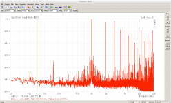
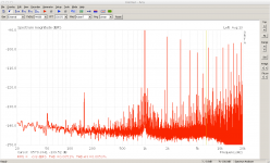
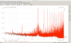
I measured the output voltage, with only one bit set, for the most significant bits. Then I used the lower bits to correct the errors.
Here some measurements for a 997 kHz signal.
First at -1dB: First picture uncorrected, second corrected, third overlay.
Second at -6dB: First picture uncorrected, second corrected, third overlay.
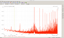
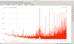
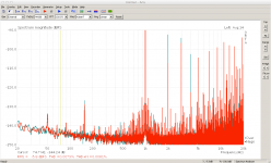
One sees only a slight improvement of the THD, but looking at the harmonics in detail, reveals that the low order harmonics are improved, whereas the higher get slightly worse.
I hat to modify the input signal and bypass the DAM filters for the test, as the correction does not commute with the filters. The right place would be to correct it in the FPGA after the filters. But only Soeren could provide that feature. I think it looks promising enough to be considered as an option in some future FPGA firmware.
There is a lot room for improvement: in the measurement procedure, the measurement equipment, .... I think the correction could be pushed much further. But as long as the firmware does not support it, I think it is not worth to put more energy in the research.
I now got my hands on some chinese 6.5 digit multimeter and so had the opportunity to some basic tests myself.
I measured the output voltage, with only one bit set, for the most significant bits. Then I used the lower bits to correct the errors.
Here some measurements for a 997 kHz signal.
First at -1dB: First picture uncorrected, second corrected, third overlay.


Second at -6dB: First picture uncorrected, second corrected, third overlay.


One sees only a slight improvement of the THD, but looking at the harmonics in detail, reveals that the low order harmonics are improved, whereas the higher get slightly worse.
I hat to modify the input signal and bypass the DAM filters for the test, as the correction does not commute with the filters. The right place would be to correct it in the FPGA after the filters. But only Soeren could provide that feature. I think it looks promising enough to be considered as an option in some future FPGA firmware.
There is a lot room for improvement: in the measurement procedure, the measurement equipment, .... I think the correction could be pushed much further. But as long as the firmware does not support it, I think it is not worth to put more energy in the research.
- Home
- Vendor's Bazaar
- Reference DAC Module - Discrete R-2R Sign Magnitude 24 bit 384 KHz