Jens
We will be waiting for the formula , in the mean time please let me know "what is the voltage across the emitter and base of T-10 & T-12 YOU taken into account to switch them on to shut down the drive to the driver trs , and at what supply voltage and power output of the amp".
Thanks
Rajeev
We will be waiting for the formula , in the mean time please let me know "what is the voltage across the emitter and base of T-10 & T-12 YOU taken into account to switch them on to shut down the drive to the driver trs , and at what supply voltage and power output of the amp".
Thanks
Rajeev
BobEllis said:Terry,
You're not really relying on the protection circuit unless you run too few output pairs. So it is a tradeoff - do you want to make your own boards for the double barrel version or use Jens' board loaded up, or Professor Leach's board and add extra output devices? (you may want to make a board to handle the source and current sensing resistors.) I'm going for the third option because my heat sinks and chassis won't accomodate Jens' board.
Bob
I really want to make my own boards if for no other reason than to learn how. Jens' boards will just fit the heasinks I have and I like that method of mounting since it's just like the ESP boards I just used. Not sure how I feel about putting the filter caps on the PCB. Seems like a lot of folks like to use multiple caps for the filter. That's what I did with my P101 and it sounds really good.
I suppose it makes it simpler to hook things up though. All of the componants arrived today except for the boards and Press-n-Peel sheets. If you really think the Low TIM can be made to run properly on +-87V rails I think I'd prefer to build that. It seems the extra stuff in the Superamp was to let it run on high voltage. Doubt any of it makes it sound any better.
Man, I'm sitting here listening to my P101 while I type and read this stuff. It's really quite nice. Hard to believe that someone who hadn't a clue a couple of months ago could've built something that sounds this good. I'm stoked!
Blessings, Terry
rajeev luthra said:what is the voltage across the emitter and base of T-10 & T-12 YOU taken into account to switch them on to shut down the drive to the driver trs , and at what supply voltage and power output of the amp
Q1: What voltage would you choose? the BE small signal diode voltage maybe?
Q2: I haven't decided yet. I'll most likely go for something in the +-68V - +-75V range but it all depends on what transformers I can get my hands on.
Q3: se Q2
\Jens
acenovelty writes
"LBHajdu/rajeev luthra,
Perhaps you have photos of your amplifier, working boards, or
schematics or board layouts to back up your claims? Lots of talk,
gentlemen. Show us your work."
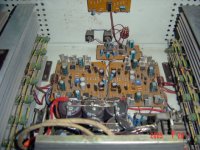
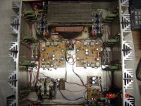
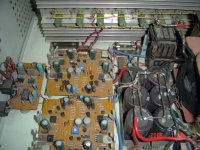
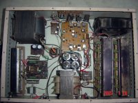
I have made a few high power amps which I have been using sucessfully
in my PA system since last three years, but all were with TO-3 devices ,
photos of insides attached .
I am making another amp now with 2SC-5200 / 2SA-1943 pairs in the
output and am posting the progress of my work on this thread as since
begining of my consept of this I have posted there .
http://www.diyaudio.com/forums/showthread.php?s=&postid=563129#p
ost563129
Then I discovered that Jens has also gone for 10pairs in the output ,
Jens worked on this design since a long time and has done the BEST
job possible , his pcbs are even better than many in pro amps , hence I
keep asking Jens regarding any queries that I have in my mind . My
project is a simple DIY job I will make everything myself -ie layout on
graphpaper , hand painted pcbs , chasis , etc etc. The same has also
been done in the other amps photos of which I have posted here .
If you can give any suggestions they are welcome .
acenovelty do you want any other proof ???
"LBHajdu/rajeev luthra,
Perhaps you have photos of your amplifier, working boards, or
schematics or board layouts to back up your claims? Lots of talk,
gentlemen. Show us your work."
I have made a few high power amps which I have been using sucessfully
in my PA system since last three years, but all were with TO-3 devices ,
photos of insides attached .
I am making another amp now with 2SC-5200 / 2SA-1943 pairs in the
output and am posting the progress of my work on this thread as since
begining of my consept of this I have posted there .
http://www.diyaudio.com/forums/showthread.php?s=&postid=563129#p
ost563129
Then I discovered that Jens has also gone for 10pairs in the output ,
Jens worked on this design since a long time and has done the BEST
job possible , his pcbs are even better than many in pro amps , hence I
keep asking Jens regarding any queries that I have in my mind . My
project is a simple DIY job I will make everything myself -ie layout on
graphpaper , hand painted pcbs , chasis , etc etc. The same has also
been done in the other amps photos of which I have posted here .
If you can give any suggestions they are welcome .
acenovelty do you want any other proof ???
Attachments
BobEllis,
Now that you have explained it, it so simple. There is however a problem, I’m crunching the numbers and there not working out. Let me show you what I’m doing and you tell me where I’m going wrong.
The SOA of the MJ15004 is 3.5A @ 55v.
If R28 has .6V across it R28 has .0022A = .6v/270 across it.
This means R37 also has .0022A across it, and 1.511V= .0022A * 680 across it.
So R45 needs to develop 2.151V= 1.511V+.6V across it to go into protect mode.
To develop 2.151V across R45 you need 6.518A = 2.151V*.33.
6.518A is way too high. So what am I doing wrong?
thanks
Leve
Your numbers are correct, but you are looking at the SOA assuming a purely reactive load - Current lags/leads voltage by 90 degrees, giving maximum current at 0V across the output. That scared/confused me when I first looked at it the same way
Look at the best case scenario - a purely resistive load. With 6.5A/ output pair in a standard Leach, you've got 13A total. Assume a 2 ohm resistive load, you'll need 26 volts across the load. Add the 2V across the emitter resistors and subtract the result from the rail voltage to get the voltage across the output devices. Assuming your rails don't sag, you've got 27V. Look at the SOA for that voltage and see where you stand. (Simplification assumption: DC output. With real signals, the peak current is higher, but the voltage across the device is lower at the peak.)
The devices on the other side will see 82 V, but will only be carrying the bias current, so they are safe. (see why you want output devices with Vceo rated for at least twice the rail voltage?)
Real speaker loads are somewhat reactive, part of the art of design is trading off reactive/ low impedance load safety and the number of output devices. See how amps with few output devices either fail or go into protection (distort) into low impedance loads?
rajeev luthra,
Very nice. 300 Watts/channel? Are those really Leach boards? My eyesight is not what it used to be, but something seems to be different. Some added flat pack transistors on the board? Where did you find that big honkin transformer? I concur that you must be an expert on your own amp.
Brings back memories of my first Heathkit amp. Wonderful days.
LBHajdu? Anything?
Is this a little opamp style buffer/preamp?
Attachments

BobEllis,
Wow, thanks a lot Bob, thanks to you I get it now. I understand that if there is a current flowing over the speaker it will lift the output voltage from ground. So the output devise doesn’t reach the rail voltage. However in a dead short the output devices will still blow. This is because only the .33 ohm resistors have voltage across them and that voltage is not sufficient to get it back into the SOA. In his site however I could remember reading that many of his students accidentally shorted the amp out and it was saved by the protection circuit. I have taken a look at the leach web site. Because I thought I remembered something about this. This is what it says “R37 through R40 - 680 ohm (changed from 470 on 4/4/2) ”. So it looks as if his new amps are not protected against dead shorts.
In this documentation leach also says that “R28 through R31, R37, and R38 set the current limit threshold which is a function of both the load voltage and the load current.”
I can’t guess at what the function of R30 and R31 are? Any Ideas? In my notes I see Jen has changed this value from 3.9K to 2.2K.
Now back to the fun part, the MJL1302A, 20MJL3281A seem to be rated at about 2/3 of the current the MJ15003 is rated at. So assuming we are not protecting from dead shorts 4A would be a safe limit.
I would like to use the VISHAY LVR LOW VALUE resisters, I think they have a low TC (but the graph is hard to interpret). I have not herd anything bad about them, one odd thing is that there molded out of the same type of plastic as transistors I think. There body is a perfect cylinder and you can get a pack of 25 for $25 from mouser. If anyone wants more info http://www.vishay.com/docs/30206/lvr.pdf There maximum value is .3 ohms.
So if I want my limit to be 4A and I use a .3 ohm resistor I get 1.2v across it at 4A. This works out really nicely because R28 = R36 and I can use 330 ohm for both. (less values of resisters to track down). If I want the same power output as the MJ15003 I need 3 pairs per rail for 12A of output.
acenovelty,
I have never built the leach amp. I did use to design manufacture, commercially, op-amp based pre-amps for musical instruments back in the day. But now-a-days I work in nuclear sub-atomic high energy Particle Physics super computing at the Relativistic Heavy Ion Collider (rhic) at Brookhaven National Laboratorys (BNL) at the behest of the department of energy on the STAR experiment. (lots of pictures at our web site) I have lost touch with electronics in favor of something a little more profitable. (no jokes about glowing in the dark please)
As you have this fascination with seeing pictures of a leach amp with MJL1302A, MJL3281A outputs I recommend you flip back through the pages of this Thread which by the way is entitle “redesign of leach amp pcb for integrated TO-247 output devices” and you’ll see lots. Responding to your post has become a burden without any benefit to me so unless you have anything useful to add I shant do so anymore.
But do be a shored I do intend to build the leach amp in my own good time. I have already ordered heat sinks now I’m looking into trying to find epoxy potted transformers. I will build it and try different parts and pick the ones that appeal to me best.
LBHajdu, I'm glad I could help.
re: dead short protection Don't forget we live in a world of imperfect power supplies. Your power supply rails will sag at high currents. Probably not as much in a "too much is not enough" DIY amp as a low end commercial product, but the situation isn't quite as bad as it first appears.
I believe R30 and D5 form sort of a protection circuit for Q10. As the output current/emitter resitor voltage rises and the Q10 base voltage tries to increase above .6V, D5 becomes forward biased and begins to conduct. This limits the Q10 base current. The value of R30 determines how much of the current is diverted. If too much base current caused a failure of Q10 you'd either have a short (most likely) and no drive to the output stage or an open and no protection the first time you got into a serious overload. With R30 and D5 limiting the base current to Q10, the protection circuit can protect the amp and leave it in an operational state.
Jens probably is looking for a little softer operation of the protection circuit. lower base current in Q10 means it does not turn on as much and therefore removes the drive more slowly.
Hopefully someone will correct me if I got it wrong, or oversimplified again. 😉
Very interestig thread. Great reading.
So it seems a couple people might be interested in the boards I am making --
BobEllis - I'm making boards to fit in my old Nikko chassis. I have broken the boards (bad wording I guess) into driver and output boards, required for my chassis but maybe easier for you as well?
Still4Given- These may help you as well, assuming they work, as you could make output boards to accomidate any number/type output devices, but still have the basic Leach driver section.
Current (mostly complete) pics of the driver board are here:
Driver Board Traces
Driver Board Components (haven't cleaned this up yet, but you get the idea)
I have higher res versions. I will be using .1" spacing connectors to link to the output board and diskdrive power to connect the power. If you want more, let me know. All stanard Leach components right now.
Keep us updated on your progress, as I would like to build another Leach in a custom chassis to I can play with the output stage as well.
Seek Your Bliss-
b
Hi WorkingAtHome,
Yes, I am interested in your design. I'm certainly not educated enough about electronics to make really good choices and must rely on the good folks here for advice about what might work best, but one of the things that piques my interest about DIY is the way folks are constantly looking for ways to tweak things to get a little better outcome. I guess there's a little "Tim the Tool Man Taylor" in all of us. 😀
Since I have pretty much decided to make a Leach amp my next project, I will be watching and reading everything I can about them. We have a saying in my field. "Measure twice, cut once." Hopefully I will be settled on what I want to do before I get too far into it. I am interested in building it, at least somewhat differently that the original design. The two-board design would at least help fitting things on a heatsink. Jens board gets quite large with the ten transistors mounted on the same board as the drive circuit, though it might take that big of a heatsink to cool everything anyway.
Blessings, Terry
My only big concern right now is the lengthening of the feedback line. My jumper will only be about an inch long, but it's just an area of concern based on some things I have seen around these boards.
Regarding feedback
How long is it with the external power transistors connected with wires?
\Jens
How long is it with the external power transistors connected with wires?
\Jens
- Status
- Not open for further replies.
- Home
- Amplifiers
- Solid State
- redesign of leach amp pcb for integrated TO-247 output devices