BobEllis
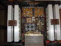
" the dust on the innards of your amps shows they have been working a
while. Love it "
I have been using in gigs since last three years . Thanks .
acenovelty
Yes they are Leach boards but my layout to accomadate the availible
components.Here in India we do not have easy acess to the required
components and have to make do with whatever is availible regarding
this I had posted the following long back http://www.diyaudio.com/forums/showthread.php?s=&threadid=34735&perpage=10&pagenumber=5:
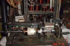
"Where did you find that big honkin transformer?"
I made it myself in fact I make all my transformers , . I also repair
transformers , loudspeaker coils , audio gear as a profession , I have a
little hand winding machine , I will post the photo of the same .
"I concur that you must be an expert on your own amp."
YES but never had much problems inspite of using it at 2ohms in bridge
mode with a power output above 1200w . I use them in a big dance
parties if you want to see photos I have some of the new year bash we
did on the 31st dec night , send me a PM and I will post the same to you
.
" the dust on the innards of your amps shows they have been working a
while. Love it "
I have been using in gigs since last three years . Thanks .
acenovelty
Yes they are Leach boards but my layout to accomadate the availible
components.Here in India we do not have easy acess to the required
components and have to make do with whatever is availible regarding
this I had posted the following long back http://www.diyaudio.com/forums/showthread.php?s=&threadid=34735&perpage=10&pagenumber=5:
"Where did you find that big honkin transformer?"
I made it myself in fact I make all my transformers , . I also repair
transformers , loudspeaker coils , audio gear as a profession , I have a
little hand winding machine , I will post the photo of the same .
"I concur that you must be an expert on your own amp."
YES but never had much problems inspite of using it at 2ohms in bridge
mode with a power output above 1200w . I use them in a big dance
parties if you want to see photos I have some of the new year bash we
did on the 31st dec night , send me a PM and I will post the same to you
.
Attachments
I guess I can safely assume at least 1 ohm, with the LR network, wiring to the binding posts and the .3 resistors.
One alternative to the MJL3281A / MJL1302A pair is the MJL21193, MJL21194, it has twice the SOA. So you only need half as many of them to develop the same current, and to tweak the protection circuit of course.
MJL3281A / MJL1302A --- 2AMP@60V
MJ15003/ MJ15004 ----3AMP@60V
MJL21193, MJL21194 ---- 4AMPS@60V (used in the sst Bryston amps)
I was wondering if anybody has any listening impressions comparing between the MJL3281A / MJL1302A and MJL21193, MJL21194 transistors in this amp or any other amp.
acenovelty writes
(" the new devices are better ." Care to present some specs or other
tangible evidence to demonstrate how they might be better? )
I had replied to this eirlear in my post 168 in this thread however I do it
again for you as you have asked the same question again .
I request you to go through the thread TO-3 v.s. TO-264 its really worth
reading
,http://www.diyaudio.com/forums/showthread.php?s=&threadid=40184&
Also go through the SOA curves and Hfe of these devices and you will
say WOW as others have said please go to posts 197, 198 , 200 , &
201 here
http://www.diyaudio.com/forums/showthread.php?s=&threadid=37670&perpage=10&pagenumber=20
Another advantage is that you save time as you can mount them on the
pcb only .
rajeev luthra,
Thoughful reply. What does it mean?
Saving time?, This is a hobby, however passionate we all may be about our particular preferences. I have the time and skill to drill 4 holes in the heatsink for each TO3. There are folks who wish to debate the advantages of plastic transistors over metal can transistors. Long experience and comparison has taught me which to choose. Sorry, I just can't find enough info to say wow.
You can lead a prositute to church, but you can't teach her virtue.
Lest some self righteous member take offence, that reference is directed to myself.
Prosit
I for one am not particularly concerned with the packing. TO-3 are harder to mount but dissipate heat a little better, TO-264 are easier to mount and don’t dissipate as well. My biggest concern with the TO-3 is that over time the leads can build up resistants, and I’m not crazy about soldering them to the board. I’m more interested about the die inside the package.
Some devices are available in both like MJL21193 and MJ21193 (same die but different package). The SOA of the MJL21193 and MJ21193 are the same, but if the MJ21193 in the TO-3 case can keep it cooler it should have a little better SOA. The MJL3281A unfortunately is only TO-264 (at least from my suppliers). I just want to use the one that sounds better.
Come to think of it I’m not really positive that TO-3 is better, there in a steal can, and steel is not as good of a conductor as plated copper (TO-264 devices). Oh well, I’ll just have to think about it some more.
I too would like to read this thread “TO-3 v.s. TO-264”.
But, I can’t find a thread called “TO-3 v.s. TO-264” and I’ve done a search.
Go to the onsemi site and look up njl3281D and njl1302D. It's only a prelim datasheet but a VERY interesting idea if it works -- an audio output device with a built-in thermal tracking diode. Claims it will eliminate thermal lag time and bias trimming.
I'm not sure if they are even available yet, but I'm going to watch for them.
I'm not sure if they are even available yet, but I'm going to watch for them.
Here is the thread , You may change your views after reading the text
http://www.diyaudio.com/forums/showthread.php?s=&threadid=38765&perpage=10&pagenumber=1
also attached another pic
http://www.diyaudio.com/forums/showthread.php?s=&threadid=38765&perpage=10&pagenumber=1
also attached another pic
Attachments
Nope, opinions seem about evenly divided on the most salient points.
Pragmatic view:
TO3 $1.87 each
4 holes,2 screws, 1 pad
TO264 $2.88 each
1 hole(maybe), clip or bar, more screws & holes, 1 pad
Pick yer poison.
Then there's point that TO3's on the outside of the heatsink just looks so cool.
Prosit
Pragmatic view:
TO3 $1.87 each
4 holes,2 screws, 1 pad
TO264 $2.88 each
1 hole(maybe), clip or bar, more screws & holes, 1 pad
Pick yer poison.
Then there's point that TO3's on the outside of the heatsink just looks so cool.
Prosit
mj21194 != mjl21194
According to my on-semi dadatsheets the SOA for the differently packaged but otherwise identical dies is most certainly not the same. Where secondary breakdown is the limiting issue, the TO3 has the expected 25% increase in available current at any given voltage. Plus if you are derating appropriately, it helps to start at 250w, rather than 200w.
The die is the same size and IIRC a copper slug is used behind it for both packages, hence Rjc (thermal resistance from die to case) is 0.7c for either. This means the much greater area of the TO3 case in contact with the heatsink is what makes the difference, ie despite all the things up to that point being identical, Rch (thermal resistance from case to sink) is so much better that it allows a 25% improvement in the overall power rating of the transistor.
If my analysis is flawed please tell me where, but at this point it sure looks to me like TO3's are 25% better at pumping heat, all else being equal...
Stuart
Your numbers look about right, which is not really that surprising when you think about the physical difference of the two casings. I however have chosen the flat pack types because I find it easier to implement on a PCB. Of cause opinions about this may differ from mine, but that is my reasoning. After this choice it is a question of finding a relationship between the number of flat pack devises needed to replace the original TO-3 types + adding some extra because I want to be able to run the amp at a higher rail voltage.
I ended up with 5 parallel devises because they can fit on a PCB that will fit on a standard heat sink from any 4 unit high 19 inch rack mount enclosure.
The discussion about TO-3 types vs. flat pack types is ongoing elsewhere and really not that interesting if you ask me.
\Jens
I ended up with 5 parallel devises because they can fit on a PCB that will fit on a standard heat sink from any 4 unit high 19 inch rack mount enclosure.
The discussion about TO-3 types vs. flat pack types is ongoing elsewhere and really not that interesting if you ask me.
\Jens
If anyone intends to place devices directly on the heatsink, without an L-bar and soldered directly on the pcb, TO3P devices are the only way to go. You can design less deep pcbs by doing so.
Placing all the devices at 90 degrees on an L shaped aluminum bar will take approximately the same space for plastic or metal devices, then it's a question of plastic vs metal sound perhaps, where actual audio listening might say whether using one or the other is better or worst.
From specs, the main advantage of plastic types is their larger bandwidth, perhaps for being less capacitive. But metal types transfer heat much better, where (debatable) heat induced distortion may make a difference benefitting the metal.
So maybe the debate is between what sounds better: more bandwidth or less heat distortion.
Carlos
All very true, but...
My comments were meant to clarify where the 'real' difference lies, it is not inside the package at all, as had been inferred in an earlier post.
Jens, as a pro, you know how to calculate this stuff, many folks here take a quick look at the datasheets and assume the difference is minimal, make a one for one swap and wonder why their new toy doesn't last...
That 50w dissipation difference between the packages translates into a pretty big deal. Assuming normalish heatsinks etc, at 125c die temp, derating properly, the power handling of the plastic package is now 200-1.43x(125c-25c), or about 57w, while the to3 under identical conditions is 107w, ie you need at least TWICE as many of the plastic packages...and you only need 50w in the device on a 1.25c heatsink to reach 125c on the die. From an engineering perpective 50w of 57w is way too close for my comfort...
Jens, Carl, you guys are dead on the money as regards PCBs, plus from a DIY perspective the plastic packages are simply easier to mount. Nowadays when I want to mount To3's I buy a predrilled heatsink, I've screwed up the drilling too many times to want to do it any more...
Carl, the transistors concerned (21193/4) are internally identical, there is no bandwidth, or any other electronic difference between the plastic or to3 packages. You are right about more modern parts from many manufacturers that are only available in in plastic packages, they are often higher in bandwidth.
Let me know where I'm wrong, I am by no means an expert...
Stuart
acenovelty
It is my humble request to you to once go through the thread TO-3 v.s.
TO-264 and then give your comments , I was also under the same
impression as you guys before I read text in this thread and some text on
the Toshiba site .
LBHajdu
Did you go through that thread ?
Secondly in your post 189 I think you have made a mistake , if there
would have been only two output devices your calculations would have
been correct , what you missed out is that there are two pairs of output
devices in the leash amp and there are TWO 680 ohm resistors , and
you should take half value ie 340 ohms in your calculations , this is why
you got 6.518A which is not correct . let me know if I am wrong ?
Yes, I when over the thread, but it wasn’t very conclusive.
I am in agreement with Jens, opinion on “TO-3 types vs. flat pack” is really not that interesting. Except to determine that it is practical to do so, and to determine how many devices you need. The added benefit of not having to drill the holes is worth it for me anyway (they never come out right).
I wasn’t very careful when I quoted the numbers last time, so I am reposting them. These SOA numbers should give a better idea. What I am taking from these numbers, is that you don’t need double the number of flat pack devices as TO-3, just a little more. About 3 should do it, providing your not upping the rail voltage any.
MJ15003 and MJ15003 - 3.6A @ 55V
MJ21193 and MJ21194 - 3.5A @ 55V
MJL21193 and MJL21194 - 3A @ 55V
MJL3281A and MJL1302A - 2.5A @ 55V
Bryston uses (4x4) of the MJL21193 and MJL21194 for there 4B SST at 80v rails for 300 watts in 8 ohms and 500 watts into 4 ohms. If I use 4 of the same devices I would be very safe at 57V rails.
As an odd note Marsh Sound Design is one of the few companies to still use the TO-3 packaging.
Does anybody have a formula for determining power into a given load when I try (A * V) it never works the rails always limit max V.
I am however surprised that in favor of the to-3 no-one has said the there is obviously convection (hot air moving to the top) in the to-3 devises.
rajeev,
You’re right I didn’t account for that, so let me try and recalculate.
First lets try Jens Rasmussen schematic.
R28 has .6 across it when protection is on, so it has .06A = (.6/100ohm) across it. So r41, r42, r44, r45 each contribute .012a = (.06/5resistors) assuming they are matched. S r46, r47, r48, r49 ,r50 has to have 4.56v = (.6v+3.96) to protect. So it will be able to pass 9.7A/device =(4.56/.47ohm)!!!
That seems way too high. Am I doing something wrong? The transformer would run out of current way before then.
-------------------------------------------------
I just realized something; the protection circuit is not needed. Lets say we’re using 4 x MJL3281A’s, they would be capable of outputting 2.5Ax4 = 10A, (in SOA at 55V) lets say I use a 600VA transformer per channel, the equivalent of 1.2KAV for a stereo pair. Such a transformer could produce 7.5A. So you can’t exceed the SOA. There is more current in the caps, but it’s very short term. I would like to know what others think about this?
Although it is not applicable to the Leech amp, there may be TO-3 advantage in that it is claimed that in EF configuration thermal tracking can be improved by mounting the sense devive on top of one of the cans. It's difficult to get this to work with plastic flat packs.
you arent using the SOA's correctly...
The charts for SOA are given at 25c, the reality is that if the heatsinking is normal, you must derate the devices. Brystons use of the devices in a huge amp means they have wonderful SOA protection circuits, always a good thing. They may also use really, really big heatsinks, perhaps with fans, that works wonders too. But it doesn't mean you can ignore some trivial math to make sure you are doing a sensible thing.
The Rjc of 0.7c per watt means that even the MJ15003 is at ~160c with 55v @ 3.6a, on an infinite heatsink, derating for 160c isn't possible, to paraphrase Bones, "It's worse that that, it's dead Jim"...if not now, wait a few secs, the solder will melt off the pins in a little while...
Any responsible designer chooses to use particular devices based on the reality of their operating environment, that means calculating and derating for the normal or perhaps even maximum temperature of the heatsink. When you do this you find the SOAs you quoted are a joke, even with an infinite heatsink none of the devices can survive for very long the ratings you are quoting.
Don't want to beat this any more, so design your amp any way you want, but the process of doing the calculations is easy, and could save you a lot of grief in the future.
Stuart
toroids...
...are rated for their continuous current capability, at a certain maximum temperature, 125c is written on some I have here. Much too hot for real world usage, I presume thats why most manufacturers use a big margin on transformers.
From a cold start, for a few minutes you can get huge currents from toroids with some voltage drop. With a 625va toroid at 55 volts, in theory you get 5.68amps from each secondary. The resistance of the secondary is ~0.5 ohms, so if you use a load that attempts to draw 11.36A, the voltage will drop to ~50, but you'll get your 11amps for long enough to smoke the outputs if they are not properly protected. Typically you can even have 20amps at ~40v, depends on the size of the core and when it saturates. It seems the bigger the core the more "overload" capacity the transformer has.
After a while of this sort of abuse the transformer will get too hot and the voltages will drop further as the resistance increases, then more heat is generated in the windings etc and ultimately if you don't have a thermal fuse, really bad stuff involving magic blue smoke starts to happen...
Not a good plan to rely on the potential inadequacy of a power supply as a protection scheme for your transistors. It's much safer to rely on your transisters as a protection scheme for your transformer, think of them as really expensive, fast acting, silicon fuses.
Stuart
- Status
- Not open for further replies.
- Home
- Amplifiers
- Solid State
- redesign of leach amp pcb for integrated TO-247 output devices