Jens:
For the inrush current, you can try to use thermistors, as used in the Pass Labs Aleph design. Look at the service manuals at:
http://www.passlabs.com/aleph.htm
Look at the power supply implementation with the thermistor.
The ones used are the Keystone CL-60 10 ohm thermistor.
The specs are here:
http://www.thermometrics.com/assets/images/cl.pdf
fcel:
I just unpacked the box with my boards. They are mostly soldiered, and I will finish them up tonight. My chassis is still in the school lab, and I looked at it yesterday. I am hoping to progress on it this friday.
--
Brian
Jens,
It`s usually the toroid that`s wound to a too high magnetic flux,That is an issue one must allways look into when ordering a transformer.
It`s usually the toroid that`s wound to a too high magnetic flux,That is an issue one must allways look into when ordering a transformer.
The inrush current is a combination of A+B. The high magnetizing inductance of the transformer core requires a higher instantaneous current to build the flux density inside the core and....the charging of empty filter caps. When the caps are empty, it looks like a short circuit until they are charged to a higher level. To reduce the amount of inrush current the initial current path is limited in some way usually with a large power resistor so that you are dictating the maximum current allowed to inrush then after a brief moment when the filter caps are charged and the flux is built within the core of the transformer the limiting resistor is switched out with a relay. I have a two channel Leach SuperAmp with a 1500VA toroid and two 55k uF capacitors. When I turn this thing on it draws a huge amount of current. The amount of inrush current can be limited by turning the unit on at exactly the peak of the line voltage (good luck trying this one). The inrush current is at a maximum when going through the zero-crossing because the current is highest at that point. If a large power supply is turned on like yours or mine without any inrush limiting close to this zero crossing it will trip your house breaker. My home and other homes I have tried it on which have tripped are 120V / 15 lines. It is a good idea to use inrush protection because it is inconvenient to have to reset the breaker every time you want to listen to audio....Good luck
BeanZ
BeanZ
Startup thing
Hi again,
Right, this is my plan.
Two relays.
The first to turn on the mains, but running through 2 resistors, the second relay is turned on when the voltage on the caps is 1/3 up and thereby shorting the resistors making the startup complete.
Would that ever work ?
\Jens 🙂
Hi again,
Right, this is my plan.
Two relays.
The first to turn on the mains, but running through 2 resistors, the second relay is turned on when the voltage on the caps is 1/3 up and thereby shorting the resistors making the startup complete.
Would that ever work ?
\Jens 🙂
It seems to make sense to me, but couldn't you just use a switch in place of the first relay?
I like the idea of the voltage over the caps activating the second relay when it gets high enough.
Look at this page with soft start circuits:
http://sound.westhost.com/project39.htm
--
Brian
I like the idea of the voltage over the caps activating the second relay when it gets high enough.
Look at this page with soft start circuits:
http://sound.westhost.com/project39.htm
--
Brian
Startup
Hi Brian
The reason for the first relay is simpel:
My preamp has two control outputs. The first is a power on signal that I'll use for just that, and the second is acitvated when muted.
I'll use them both so the amp will be controlled by the preamp.
\Jens
Hi Brian
The reason for the first relay is simpel:
My preamp has two control outputs. The first is a power on signal that I'll use for just that, and the second is acitvated when muted.
I'll use them both so the amp will be controlled by the preamp.
\Jens
ESP has a soft-start project for power amps, which might be useful to you.
ESP soft start power suppy
ESP soft start power suppy
Freq response.
I found the error
The standing current in the output was too low resulting in a bad high freq. response.
Now it's flat to about 40 kHz 🙂
On monday I'll get the school's workshop to make four small signal PCB's, and hopefully they will all work.
Also working on the control cuircuit for the amp
\Jens
I found the error
The standing current in the output was too low resulting in a bad high freq. response.
Now it's flat to about 40 kHz 🙂
On monday I'll get the school's workshop to make four small signal PCB's, and hopefully they will all work.
Also working on the control cuircuit for the amp
\Jens
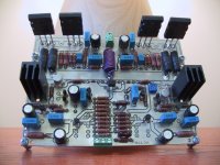
Supply board
Today I made the sypplyboard.... There will be a bank of 6 * 10000µF 80V caps pr. channel. In all 240 mF.
I also have 20000µF on each outputboard. I hope it will be enough to make a decent railquality.
I'll post pics later 🙂
\Jens
Today I made the sypplyboard.... There will be a bank of 6 * 10000µF 80V caps pr. channel. In all 240 mF.
I also have 20000µF on each outputboard. I hope it will be enough to make a decent railquality.
I'll post pics later 🙂
\Jens
I have my boards mostly populated, and will match my input transistors, zeners and test the boards. Pictures are at: http://brian.darg.net/leachpcb
--
Brian
--
Brian
Attachments
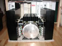
OT: Heat sinks
Hi Jens.
I just surfed by this thread. Where did you get the heat sinks shown in the picture?
Mvh. Uffe
Hi Jens.
I just surfed by this thread. Where did you get the heat sinks shown in the picture?
Mvh. Uffe
Hi Jens
I can´t find your adress and I can´t mail you via the "send mail" link in your profile. Send an e-mail to me at: Nisbeth@hotmail.com and I´ll reply to that.
Mvh. Uffe
I can´t find your adress and I can´t mail you via the "send mail" link in your profile. Send an e-mail to me at: Nisbeth@hotmail.com and I´ll reply to that.
Mvh. Uffe
Hi everyone...A while ago I made my own version of the leach amplifier that incorporates the output transistors and rectifying capacitors onboard. It is single sided and fairly easy to build for diy'ers. I just set up a very basic website with pictures and layouts...feel free to use them, but please send my pictures of your final amps...
Here is the website:
http://www.ece.mcgill.ca/~dlamb/
Here is the website:
http://www.ece.mcgill.ca/~dlamb/
I finished soldiering my boards and tested them, and they work fine. I am going to send them out to a board production place and get a few boards made.
--
Brian
--
Brian
Listening to ½ an amp
Hi
Great to hear your amp is working Brian, how much are the boards ?
I now have two of four PCB's fully populated ad playing....sweet 🙂
I'll post pic's later.
There are no problems, and the sound is great (I'm problably biased but newer the less it's great)
\Jens
Hi
Great to hear your amp is working Brian, how much are the boards ?
I now have two of four PCB's fully populated ad playing....sweet 🙂
I'll post pic's later.
There are no problems, and the sound is great (I'm problably biased but newer the less it's great)
\Jens
The best quote that I have gotten is around $15 a board for 60 boards. I am still looking. The reason it is that high is that I want to use 0.093 substrate. I can get it cheaper if I use thinner.
--
Brian
--
Brian
- Status
- Not open for further replies.
- Home
- Amplifiers
- Solid State
- redesign of leach amp pcb for integrated TO-247 output devices