Ah, I thought you would be using the Eminence Kappa 10LF. I would recommend to use a PA woofer for this PA application, even if on paper you might lose a few dB's or some low frequency extension. Reliability and total costs over its lifetime are way more important.
Passive speaker-level limiters have several drawbacks when used for woofers: they add resistance, which reduces electrical damping (requiring a larger woofer enclosure) and decreases efficiency (requiring more $$ for amplification) and they add some distortion (not sure how much). See Loudspeaker Protection and Muting. Placing a line level limiter before the amplifier really is better in all these aspects. You say it cannot be done because you use a receiver, but you can limit the signals that go to the receiver inputs. This circuit can do it: Ultra Simple Bass Guitar Compressor.
Passive speaker-level limiters have several drawbacks when used for woofers: they add resistance, which reduces electrical damping (requiring a larger woofer enclosure) and decreases efficiency (requiring more $$ for amplification) and they add some distortion (not sure how much). See Loudspeaker Protection and Muting. Placing a line level limiter before the amplifier really is better in all these aspects. You say it cannot be done because you use a receiver, but you can limit the signals that go to the receiver inputs. This circuit can do it: Ultra Simple Bass Guitar Compressor.
Last edited:
I was sorely tempted to go with that Kappa driver, and may end up using it in a future build. The predicted response curve in a bandpass design was pretty tempting.
However, this subwoofer is going to be used in the bar's background music system. They already have a powered PA system (two 12+1 powered tops and two double-12 powered bandpass systems for bass) to be used on those nights when they're "busy".
To give you an idea of the usage requirements here, the "main" speakers in that background music system are two old Bose 101 speakers, and the "subwoofer" used to be the 8th order BP module from a Bose AM5 series set. Right now they're using my POC6 sub as a temporary sub while I'm fixing the blown one, and that's proving to be a bit too much - they've had to turn down the volume on the receiver's subwoofer output.
As the speaker protection devices are cheap, I've decided to do things the ol-fashioned way - bought a bunch of them for testing to see which one works best. The added impedance is quite low (unless they trigger, of course), and results in only a minor change to the predicted response of the subwoofer. The sim certainly predicts that the response would be smoother than the Bose sub that was replaced 🙂.
The bottom 2/3rds of the coil also seems to be blackened, and I'm a bit curious as to why the top 1/3rds is not..
Theory 1: the front of the coil is cooled much better by airflow round the spider I suspect. Unless the back of the magnet is very well vented it will have less cooling.
Once part of the coil heats up it will increase in resistance and make the difference worse.
Theory 2: there was DC offset, the coil may have parked at the back and the magnet poles acted to cool the front part of the coil.
Theory 3: Perhaps the damaged coil former got physically jammed all the way back and then the coil cooked?
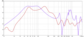
Here's how the sim'd response of the DA270-equipped sub (blue) compares to the measured response of the Bose AM bass module (red) that it's replacing. I suspect that the Bose bass module was damaged, but I didn't have enough time with it to test it completely. So please don't take this as the "official" response of that model. It's from an AM7 set, btw, not an AM5 set.
The inline protection that I'm planning to add to the Enigma upgrade would have to have pretty high impedance in order to make the response as lumpy as the subwoofer that it's replacing.
The inline protection that I'm planning to add to the Enigma upgrade would have to have pretty high impedance in order to make the response as lumpy as the subwoofer that it's replacing.
Attachments
I'm trying to come up with a decent testing process for determining the power limit of the DA270 in the Enigma bandpass, without blowing the driver in the process.
Here's the idea that I have, that's yet to be tested: Starting with a low voltage, apply a signal at Fb (where cone movement will be minimum) to the subwoofer and measure the current. Use the results to determine the impedance, and power dissipation. Repeat for 1dB increases in voltage. Stop when the impedance has increased noticeably (I'm trying to decide what "noticeably" should mean. 25% for example). Use the results to extrapolate to 50% increase in impedance. Take note of the voltage at the extrapolation point. Use that to determine what the power dissipation would be at that point and set that as the thermal limit for the system.
Here's the idea that I have, that's yet to be tested: Starting with a low voltage, apply a signal at Fb (where cone movement will be minimum) to the subwoofer and measure the current. Use the results to determine the impedance, and power dissipation. Repeat for 1dB increases in voltage. Stop when the impedance has increased noticeably (I'm trying to decide what "noticeably" should mean. 25% for example). Use the results to extrapolate to 50% increase in impedance. Take note of the voltage at the extrapolation point. Use that to determine what the power dissipation would be at that point and set that as the thermal limit for the system.
Theory 3: Perhaps the damaged coil former got physically jammed all the way back and then the coil cooked?
I suspect that may be best explanation, though I didn't smell any burnt coil scent when I opened the cabinet up. The magnet was located in the sealed section of the cabinet, and I oped the cabinet within 24 hours of noticing the problem, so I think I should've smelled something.
Uhm, that's wrong, that doesn't work that way. The VC dissipates the most heat to the pole plates and magnet. The long term temperature will only rise moderately until the 'reservoir' of the magnet is 'used up' and can't dissipate the heat itself. After that, the temperature will rise much quicker. And on top of that, it doesn't 'burn off' like a light bulb. If you use it often near maximum power, the heat makes the insulation laquer of the VC windings brittle, with every high power session burning off more and you can't turn that back. Even if the power isn't increased from session to session, it will burn to a crisp anyway if you use it permanently close to the max power.
The goal is to stay at ~75% of the power or lower to keep longevity drivers. Not loud enough? Put up more subs.
E: God, I wanted to go to bed HOURS ago!
The goal is to stay at ~75% of the power or lower to keep longevity drivers. Not loud enough? Put up more subs.
E: God, I wanted to go to bed HOURS ago!
Last edited:
Uhm, that's wrong, that doesn't work that way. The VC dissipates the most heat to the pole plates and magnet. The long term temperature will only rise moderately until the 'reservoir' of the magnet is 'used up' and can't dissipate the heat itself. After that, the temperature will rise much quicker.
Yup, I suspected that there would be some sort of "runaway" at some point where the magnet structure cannot dissipate heat faster than it's been generated across the coil However, if the temperature of the voice coil rises, even moderately, the impedance should also rise too. If so, then it should be possible to track this (impedance of a copper coil should increase around 0.4% for every degree (C) rise in temperature). Perhaps hit it with a tone at Fb for 30 seconds and record the current flow at the end of that period, which can then be used to determine the impedance and corresponding impedance rise.
However, if the temperature of the voice coil rises, even moderately, the impedance should also rise too.
It does. And that affects the Qt greatly. Plus, increasing the power does not give you the same return in spl, that's called power compression. The PC can reach over 2db. Meaning, if you double the power (+3dB), you get less than 1dB more out of it.
If so, then it should be possible to track this (impedance of a copper coil should increase around 0.4% for every degree (C) rise in temperature). Perhaps hit it with a tone at Fb for 30 seconds and record the current flow at the end of that period, which can then be used to determine the impedance and corresponding impedance rise.
No, you cannot. You need to know the thermal capacity and surface of the magnet and basket and how much air exchange happens (on BR, 6th order BP etc). And the long term power capability does not show on 30s stints anyway. Heat dissipation is important, by radiation or by airflow. That's also the reason high power subs drivers on 4th order BP are mounted with the magnet to the ventilated chamber.
No, you cannot. You need to know the thermal capacity and surface of the magnet and basket and how much air exchange happens (on BR, 6th order BP etc).
I don't think I'll "need to know" those things - that's what the testing is for. I'm thinking that, the faster that heat can wicked away heat from the coil (via the magnet structure, etc.), the less temperature rise the coil will experience over a particular period, and the lower the impedance rise it will see as a result. I also expect that this ability to wick heat away will be dependent on cone excursion too, which is why I'll run the test in the worst-case scenario - at Fb, where excursion is at a minimum.
And the long term power capability does not show on 30s stints anyway.
Undoubtedly. But I'm not aiming to have the subwoofer run for long periods at a power level higher than spec'd. The circuit breaker I brought for it supposedly trips if it sees 200% rated current (1.3A) for more than 5 seconds. I want to make sure that breaker trips before the coil sees a significant rise in impedance, signifying that it's getting too hot.
Another thing: measuring the impedance after a 30s burst may also give a good idea of the coil's temperature (using the same temperature coefficient) and how close it's getting to the rated max temperature of the insulation. I don't know that offhand, but maybe a Google search will turn that up.
I don't think I'll "need to know" those things - that's what the testing is for. I'm thinking that, the faster that heat can wicked away heat from the coil (via the magnet structure, etc.), the less temperature rise the coil will experience over a particular period, and the lower the impedance rise it will see as a result. I also expect that this ability to wick heat away will be dependent on cone excursion too, which is why I'll run the test in the worst-case scenario - at Fb, where excursion is at a minimum.
That's not how any of this works. Firstly, the curve isn't a linear one. You are taking just a crumb out of the cake without knowing if the cake is round or square. If you want the worst case, heat the magnet first with a torch. 🙄
Besides that, the VC former didn't shatter because of the minimum excursion. It is still unknown if the one caused the second or the other way around.
Undoubtedly. But I'm not aiming to have the subwoofer run for long periods at a power level higher than spec'd. The circuit breaker I brought for it supposedly trips if it sees 200% rated current (1.3A) for more than 5 seconds. I want to make sure that breaker trips before the coil sees a significant rise in impedance, signifying that it's getting too hot.
That's not how it works. If you use a slow breaker, the average power can be very high because of impulses. If you use a fast breaker, it will trigger at way too low power or short impulses. If you want to be sure, buy a controller which got a peak- and a rms-limiter.
Another thing: measuring the impedance after a 30s burst may also give a good idea of the coil's temperature (using the same temperature coefficient) and how close it's getting to the rated max temperature of the insulation. I don't know that offhand, but maybe a Google search will turn that up.
That's exacly what's wrong, it's not a linear curve. And even if you account for that, the music isn't a sine wave. You're throwing just pieces of theory together with practical hacks. That gives you barely an estimate.
To be constructive: Why don't you use a digital thermometer near the coil? Laser or thermal sensor. If you can't get to the VC because of the construction, you could measure the temperature of the pole plate.
That's not how any of this works. Firstly, the curve isn't a linear one.
Which curve are you talking about? The increase in impedance due to the increase in temperature? Because the information at the page below suggests that the relationship is very linear to significant temperatures:
reference source for copper conductivity vs. temperature? - Electrical Engineering Stack Exchange
Besides that, the VC former didn't shatter because of the minimum excursion.
Knowing that driver, and what they told me they heard before it failed, I'm pretty sure that's exactly what happened. While the coil itself is darker at some points, there's no indication that the insulation failed at any point. The last rung of the coil that's right up against the end of the former is what failed.
If you use a slow breaker, the average power can be very high because of impulses. If you use a fast breaker, it will trigger at way too low power or short impulses.
I've been advised that it's some sort of thermocouple breaker - it will trigger with 5s of 200% rated current, or basically anything input signal that equals to that amount of energy over the same period. And it's designed for use with 100W systems. Given that its rated current is 1.35 Amps, I believe they've taken the transient nature of music into consideration.
If you can't get to the VC because of the construction, you could measure the temperature of the pole plate.
That would be worse than what I'm trying to do. Not only will it not be at the same temperature as the coil, it would be lagging it, by an amount that's dependent on how effective it's acting as a heat sink.
Which curve are you talking about? The increase in impedance due to the increase in temperature? Because the information at the page below suggests that the relationship is very linear to significant temperatures:
[..non-relevant link..]
I'm talking about the heat dissipation of the voice coil because that's what actually matters. It works great with a cool magnet, the hotter the magnet, the less heat the VC can actually dissipate. Think about a hose filling up a bucket with a small hole at the bottom. Once it's full, it's not only dripping from the small hole, it overflows. Except that its not a linear, it's a kinda expotential or hyperbolic curve. Or in other words, like I already said, your experiment does not apply in praxis.
Knowing that driver, and what they told me they heard before it failed, I'm pretty sure that's exactly what happened. While the coil itself is darker at some points, there's no indication that the insulation failed at any point. The last rung of the coil that's right up against the end of the former is what failed.
That happens, when the excursion is too high, not too low. If it was too low, both ends of the VC would have scorch marks.
I've been advised that it's some sort of thermocouple breaker - it will trigger with 5s of 200% rated current, or basically anything input signal that equals to that amount of energy over the same period. And it's designed for use with 100W systems. Given that its rated current is 1.35 Amps, I believe they've taken the transient nature of music into consideration.
That breaker will introduce a serial resistance. That increases your Qt and also the response.
I can tell you from experience and service repair that these things calm the nerves because "I've done the right thing" but do not work in the long run. It can't know how hot the VC is. On 8 Ohm 1,35A x2 is 58.32W. On the impedance peak of a BP of ~35 Ohm, that's 255.15W. How did you say that would be safe?
Oh, and according to this picture it pretty much seems you did not mount the driver with the magnet to the venitlated part of the enclosure. That actually reduces the long term power rating.
That would be worse than what I'm trying to do. Not only will it not be at the same temperature as the coil, it would be lagging it, by an amount that's dependent on how effective it's acting as a heat sink.
Ofcourse you can't tell how hot the VC exactly is but you know when the magnet is 'saturated' with heat and the VC can't dissipate anymore to it. After that point, the temperature of the VC rises rapidly. Aside from that, I suggested to measure the VC with a laser thermometer.
I can't say anything more. Good luck repairing your subwoofer.
I'm talking about the heat dissipation of the voice coil because that's what actually matters. It works great with a cool magnet, the hotter the magnet, the less heat the VC can actually dissipate. Think about a hose filling up a bucket with a small hole at the bottom. Once it's full, it's not only dripping from the small hole, it overflows. Except that its not a linear, it's a kinda expotential or hyperbolic curve. Or in other words, like I already said, your experiment does not apply in praxis.
Ok, I think I understand what you're trying to say now. My experiment is to determine specifically what temperature the voice coil would be after a 30 second tone, to get an idea of how fast heat is removed from it during that specific period. If my experiment was to measure heat dissipation over time, I would use a longer period and take several measurements of current flow through the coil during that period, then use that to determine impedance, and subsequently temperature from that. Basically exactly what the author of the following paper did to estimate coil temperature, so it should also work if I want to determine the coil's temperature after a specific period of 30 seconds.
(PDF) Voice coil temperature in loudspeaker performance: Causes, effects and prevention techniques
Of course how fast the coil can dissipate hear during a 30 second period will depend on the temperature of the surrounding stuff, e.g. the magnet structure. I will have to ensure that the testing is done when the magnet's at room temperature for each run at different voltage levels.
That breaker will introduce a serial resistance. That increases your Qt and also the response.
I've inquired and have been told that the resistance is very low and makes little or no difference to the speaker's output. It would have been better if it was published of course. I will measure it once I receive it.
On 8 Ohm 1,35A x2 is 58.32W. On the impedance peak of a BP of ~35 Ohm, that's 255.15W. How did you say that would be safe?
If I was using a current amplifier, I'd be worried. As audio amplifiers are typically voltage amplifiers, I'm not. An audio amplifier capable of generating 1.35A into 8 ohms is not going to generate 1.35A into 35 ohms at the same gain setting. That's why I intend to do the testing at Fb, as that's the worst case scenario - driver movement is at a minimum, and current flow is at a maximum.
Oh, and according to this picture it pretty much seems you did not mount the driver with the magnet to the venitlated part of the enclosure. That actually reduces the long term power rating.
Correct. When I built it 15 years ago, I didn't have bar usage in mind 🙂.
Ok, I think I understand what you're trying to say now. My experiment is to determine specifically what temperature the voice coil would be after a 30 second tone, to get an idea of how fast heat is removed from it during that specific period. If my experiment was to measure heat dissipation over time, I would use a longer period and take several measurements of current flow through the coil during that period, then use that to determine impedance, and subsequently temperature from that. Basically exactly what the author of the following paper did to estimate coil temperature, so it should also work if I want to determine the coil's temperature after a specific period of 30 seconds.
(PDF) Voice coil temperature in loudspeaker performance: Causes, effects and prevention techniques
He also wrote:
6.3.3 Drawbacks and limitations There were a number of drawbacks and limitations during the experimental process. With the available equipment, it was impossible to directly measure the voice coil temperature. Instead, a thermocouple was placed very close to the voice coil on the magnetic structure. This gave a reading that gave a good idea of the heat transfer that was taking place in the driver. To find the actual voice coil temperature, the DC voice coil resistance had to be monitored and then used to calculate the temperature.
So, yes, he did your method but now please look at this graph:
You can clearly see the exact correlation of the pole plate temperature and VC temperature. You can also see that it is not, as I already said, a linear development but a curve. And, if you've paid attention and actually read the paper, he said that that the back plate always had a higher temperature than the VC of about 15°C. (7. p45, 2nd & 3rd paragraph). When the magnet temperature reaches its top plateau, the VC temperature still rises though, meaning you have to stop there. That means, it doesn't matter how much the resistance is increasing since you only have to observe the 'saturation' of the magnet because of the correlation. And that's exactly what I was telling you already.
Of course how fast the coil can dissipate hear during a 30 second period will depend on the temperature of the surrounding stuff, e.g. the magnet structure. I will have to ensure that the testing is done when the magnet's at room temperature for each run at different voltage levels.
*sigh* You obviously did not read the paper yourself. Or understood it.
I've inquired and have been told that the resistance is very low and makes little or no difference to the speaker's output. It would have been better if it was published of course. I will measure it once I receive it.
I was not talking about the output reduced by the breaker, I was taling about the Qt and the reduced output because of a hot VC. Besides that, measuring the temperature of the pole plate is, according to the paper and what I already wrote, much more important.
If I was using a current amplifier, I'd be worried. As audio amplifiers are typically voltage amplifiers, I'm not. An audio amplifier capable of generating 1.35A into 8 ohms is not going to generate 1.35A into 35 ohms at the same gain setting. That's why I intend to do the testing at Fb, as that's the worst case scenario - driver movement is at a minimum, and current flow is at a maximum.
All well and fine but the breaker still doesn't use the fb but instead what's current is actually flowing. Or in other words, unless you compensate the impedance, you cannot rely on the breaker.
Correct. When I built it 15 years ago, I didn't have bar usage in mind 🙂.
That's still the wrong mounting, you do not gain any advantage by that. No reason to do that at all.
Attachments
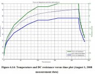
So, yes, he did your method but now please look at this graph
...yes, and look at the horizontal scale of that graph. It's in 50 MINUTE segments. I want a build a solution that will trip the circuit breaker if the driver sees 100W for more than a few SECONDS. How is it applicable to what I want to do?
You can clearly see the exact correlation of the pole plate temperature and VC temperature. You can also see that it is not, as I already said, a linear development but a curve.
No-one is disputing that! What you have failed to show however is how is it relevant to what I'm trying to accomplish.
And, if you've paid attention and actually read the paper, he said that that the back plate always had a higher temperature than the VC of about 15°C.
Yes, I saw that. I'm curious about it, as to what mechanism would result in a heat sink being at a higher temperature than the source of the heat (the voice-coil). However it's not applicable to what I want to accomplish, which is to stop the coil trying to dissipate more than 100W over a short period.
I was not talking about the output reduced by the breaker, I was taling about the Qt and the reduced output because of a hot VC.
It doesn't appear so from what you previously said, which was "That breaker will introduce a serial resistance. That increases your Qt and also the response." Looks like you were referring to the breaker's resistance increasing Qt. Of course any rise in voice coil impedance will increase Qt.
All well and fine but the breaker still doesn't use the fb but instead what's current is actually flowing. Or in other words, unless you compensate the impedance, you cannot rely on the breaker.
As the current flow will be less when impedance is higher, IMO it's a non-issue. Hornresp suggests impedance is going to be around 27.5 ohms at the peaks. Box losses will likely bring it down to more like 18 ohms. Assuming a 28.3V input, that works out to 44.5W (1.57A), well within the driver's rated capability, and way below where I want the breaker to trip.
That's still the wrong mounting, you do not gain any advantage by that. No reason to do that at all.
There was not enough space in the vented section to contain both the vents and the driver mounted magnet out. In any case, it lasted for 15 years in that config, being used to what it was designed to do - a home stereo / HT subwoofer. Based on what I heard happened, it was destroyed because someone took off the mixer (some cheap unit) before they shut down the amp. There was a loud pop from the subwoofer (likely caused by the former slamming into the backplate) and they said the subwoofer sounded "different" after that, and then stopped working. It was working fine for them up to that point. I'll be checking to see if the replacement driver has the same problem as the old one that allowed that to happen (hopefully it doesn't). The new driver has a lower power rating than the old one however, which is why I'm trying to find a way to limit power flow into the driver if it sees more than a certain amount over a brief period. A lamp-based limiter solution like what Bose uses might have been ideal for this situation, but there isn't much available on how to size said limiter and appropriate lamps don't appear to be easily available anyway. Hence my attempt to use a two stage solution based on the circuit breaker and a bypass circuit that adds a few ohms to the circuit if the breaker trips to reduce the current flow into (and therefore the power dissipation of) the driver's voice coil. Will it work? Not sure, but hopefully the testing will show if it does the job.
...yes, and look at the horizontal scale of that graph. It's in 50 MINUTE segments. I want a build a solution that will trip the circuit breaker if the driver sees 100W for more than a few SECONDS. How is it applicable to what I want to do?
You said it was not driven with more than 100W. If it stays a tad below but the ambient tempreature rises by 10°, guess what will happen then? It's not the power alone, it's the temperature of the VC. And the paper you've posted showed that's the most effective way to do that.
Did you know that the lack of air exchange (=cooling) reduces the maximum long term power capability in some cases by more than 1/3, in extreme cases (hot ambient temperature, small enclosure, sealed) even to 1/2? With keeping the magnet in the sealed part, a big part of the heat in the magnet cannot be dissipated - no air exchange (like with a port). The air speed and the turbulences of the air from the port the cooling is improved greatly.
No-one is disputing that! What you have failed to show however is how is it relevant to what I'm trying to accomplish.
I thought you wanted to keep your sub alive. You obviously don't want to do that.
Yes, I saw that. I'm curious about it, as to what mechanism would result in a heat sink being at a higher temperature than the source of the heat (the voice-coil).
I didn't think that either initially. Adam Hill described the mechanisms partly in 4.6, p22ff. He did a mistake though:
Additionally, the larger the air gap (both wide and deep) the greater the heat transfer capacity.
That's wrong because a higher distance would mean, the pole plate could not take up as much heat as a close distance by radiation. That's easy to verify, start your soldering iron and put a finger 3cm away from it and then 1cm. The shorter distance does indeed transfer much more heat and it's practically just readiation. The air gap depth does provide more heat transfer though, that was correct. The same goes for the air, a tighter air gap creates a higher air velocity and the faster air will transport more heat away from the VC. The losses are higher but the cooling is improved. That's also why you won't find raised spiders in PA drivers, that would eliminate a lot of the air velocity and movement. The cooling is much more important in PA than in Hifi and that's why they have often such elaborate bore patterns for the back pole plate at the diameter of the VC and sideways air channels between basket and pole plate.
I'm not very fond of that paper since he didn't describe how he measured the VC temperature. I got the suspicion he just calculated it from the resistance and did not measure it directly, since he only mentioned the equation.
Anyway. A possible explaination for the magnet being hotter than the VC could be because the VC could dissipate more heat through the air because of its movement.
However it's not applicable to what I want to accomplish, which is to stop the coil trying to dissipate more than 100W over a short period.
It does not dissipate 100W, ~2-3% go into the movement. 😀 Seriously, I was convinced you wanted to keep the driver intact. Summer heat or a heater in close proximity and your sub says goodbye even with power lower than 100W, especally because you decided to forfeit the cooling.
It doesn't appear so from what you previously said, which was "That breaker will introduce a serial resistance. That increases your Qt and also the response." Looks like you were referring to the breaker's resistance increasing Qt. Of course any rise in voice coil impedance will increase Qt.
With the higher Qt you'll get more excursion and a higher spl (that's essentially the principle of a BP subwoofer). So that indeed changes the response.
There was not enough space in the vented section to contain both the vents and the driver mounted magnet out.
Either driver off-center and one (bigger) port at the wall (not a tube) or edge ports. Not much work and can still be done now, just use a board over the wall where the holes for the ports are. You probably had to take out the ports anyway.
As there is little space to invert the woofer, is transforming the enclosure to a parallel 6th order bandpass (both chambers vented to the outside world) an option?
Undersized vents actually aid in cooling due to turbulence.
Undersized vents actually aid in cooling due to turbulence.
You said it was not driven with more than 100W. If it stays a tad below but the ambient tempreature rises by 10°, guess what will happen then?
I'm guessing that the breaker will trip in that scenario you described. The breaker is rated at 1.35A, and trips if it sees double that for 5 seconds. Assuming an 8 ohm voice coil impedance, that means that it will trip if the driver sees anything above ~60W continuous for more than 5 seconds. It will have to see a current of 2.7 and an impedance of 13.7 ohms for the breaker to trip at a "true" 100W over 5 seconds. And an amp that delivers 100W into 8 ohms (which is what is being used to drive this subwoofer) is going to deliver only ~60W into 13.7 ohms. So this driver isn't going to see anywhere near 100W, or a tad below, for any continuous period. The breaker should trip first. Its "100W" rating appears to be for transient (music), not continuous, signals.
Did you know that the lack of air exchange (=cooling) reduces the maximum long term power capability in some cases by more than 1/3, in extreme cases (hot ambient temperature, small enclosure, sealed) even to 1/2?
Sure, but mounting the driver with the magnet in the vented section was not an option for this design. And it did work well for 15 years. Redesigning the vent layout to allow the driver to mounted magnet-out really isn't an option at this point, though I may explore it if the replacement driver fails for thermal reasons.
Note: the replacement driver does have an aluminum cone. That may provide a more efficient means for heat to exit the sealed section of the subwoofer cabinet than the previous driver's plastic cone.
I'm not very fond of that paper since he didn't describe how he measured the VC temperature.
Actually he did. under section 6.3.3. "With the available equipment, it was impossible to directly measure the voice coil temperature. Instead, a thermocouple was placed very close to the voice coil on the magnetic structure. This gave a reading that gave a good idea of the heat transfer that was taking place in the driver. To find the actual voice coil temperature, the DC voice coil resistance had to be monitored and then used to calculate the temperature."
So it looks like he just calculated it from the resistance.
It doesn't make sense to me that the supposed source of heat (the voice coil) would be at a lower temperature than the sink (the magnet structure). Heat flows from hot to cold, not vice-versa. He mentioned that he used the DC voice coil resistance, which implies that he used DC voltage to take the measurement. As the coil is a lot smaller than the magnet structure, it likely cools a lot faster, so perhaps the difference is due to the amount of cooling that took place between when he was doing the FR measurements and when he switched to using a DC input to measure impedance. With that in mind, I'd have done the test slightly differently - used a pure tone @ Fb, use that to calculate impedance, then switched to the MLS and sweep signals for FR.
It does not dissipate 100W, ~2-3% go into the movement. 😀
It's still dissipating 100W - some into sound and the rest into heat 😀
As there is little space to invert the woofer, is transforming the enclosure to a parallel 6th order
I tried looking at that - the chambers are too small. I couldn't get any driver to work and produce a response that I felt comfortable with.
Converting the box into a series-tuned 6th order BP and using an Eminence pro audio driver did look interesting (discussed earlier in this thread), but the cost to do that would have been considerably more than the ~$40 I've spent on the replacement driver.
Last edited:
- Home
- Loudspeakers
- Subwoofers
- Rebuilding the Enigma...