Re: decent reclocking influances
hello IJ,
Well, what shall I say ? I've done quite some listening tests on the 63's, and 2 years ago also on the 1704's (I use these in the PCM63 plugins, but also in the I2S DAC of the tentlabs CD player).
Honestly, I have a hard time hearing the differences. In both cases, extensive attention was paid to power supplies, layout, jitter and analogue output stages.
If differences are present they are so small to my ears that I wouldn't want to bet on them.
best
irgendjemand said:
Guido,
Wait! There is one more step to clear-up here:
Herb is saying since long, that if you apply a decent reclocking after the Digital Filter, the all discussion about PCM63 Selection-Grades (K/K2/KY/Y) becomes a waste of time and money(!) as well! There will be no differences to consider, so Herb. His/yours decent reclocking make all PCMs 63 to sing the same (!).
BTW he also got some negative reactions about this!!
Can you support him in this point / clear this up, please?
Greeting,
IJ
hello IJ,
Well, what shall I say ? I've done quite some listening tests on the 63's, and 2 years ago also on the 1704's (I use these in the PCM63 plugins, but also in the I2S DAC of the tentlabs CD player).
Honestly, I have a hard time hearing the differences. In both cases, extensive attention was paid to power supplies, layout, jitter and analogue output stages.
If differences are present they are so small to my ears that I wouldn't want to bet on them.
best
Re: decent reclocking influances
To my understanding and experimental experience, I would say this is complete nonsence! After re-clocking you simply lower down the jitter and this gives you the possibility to distinguish between the DACs grades that would be badly masked if no or bad re-clock at all. With re-clocking there is no problem to listen even differences between all 63's K-grades from different manufacturing countries/lots!Herb is saying since long, that if you apply a decent reclocking after the Digital Filter, the all discussion about PCM63 Selection-Grades (K/K2/KY/Y) becomes a waste of time and money(!) as well! There will be no differences to consider, so Herb. His/yours decent reclocking make all PCMs 63 to sing the same (!).
In common sense and in science, when the jitter issue is 100% solved (of course therically not possile), it should open up the difference to tell how good is a cable, how good is the DAC, how good is the power supply, how good is the capacitors, how good is the resistors ...., the amplifier, the speaker etc.....
If there is no difference to tell about different grade of DAC or even type of DAC, either the tester (human ear) is not good enough OR some thing is masking the signal so that the difference of other part of the system is impossible to detect.
One possibility is that the reclock circuit is not reducing jitter but increasing jitter levels!
Reducing jitter in DAC is just one of the item need to be solved but it is not the only reason for good sound DAC.
The basic problem, even in Bob Pease'sstatement is that, yes, you cant hear the difference when you cant measure the difference. But when someoneelse, even just one out of a million who can hear the difference, and the result is repeatable, that means either the science is not there yet or your measurement is lousy. This is how the basic scienceproof works.
spencer said:In common sense and in science, when the jitter issue is 100% solved (of course therically not possile), it should open up the difference to tell how good is a cable, how good is the DAC, how good is the power supply, how good is the capacitors, how good is the resistors ...., the amplifier, the speaker etc.....
If there is no difference to tell about different grade of DAC or even type of DAC, either the tester (human ear) is not good enough OR some thing is masking the signal so that the difference of other part of the system is impossible to detect.
One possibility is that the reclock circuit is not reducing jitter but increasing jitter levels!
Reducing jitter in DAC is just one of the item need to be solved but it is not the only reason for good sound DAC.
The basic problem, even in Bob Pease'sstatement is that, yes, you cant hear the difference when you cant measure the difference. But when someoneelse, even just one out of a million who can hear the difference, and the result is repeatable, that means either the science is not there yet or your measurement is lousy. This is how the basic scienceproof works.
Hi,
We measured the jitter before and after the reclocker, and the conclusion is that the jitter is reduced. never underestimate the importance of jitter, we daily notice that lower is better, especially the low frequency content of the jitter is very important.
Low jitter is a basic condition for good sound, as are other parameters, like layout, analogue stages, power supplies.
best
DDDDC reclocking boards
Hi Guido,
How about producing and selling a separate board, dedicated to re-clocking for DIYs, as newly developed and designed by the DDDDC (Dutch-Diy-Developers & Designer-Connection)?
Greetings,
IJ.
Guido Tent said:Hi, We measured the jitter before and after the reclocker, and the conclusion is that the jitter is reduced. never underestimate the importance of jitter, we daily notice that lower is better, especially the low frequency content of the jitter is very important.
Low jitter is a basic condition for good sound, as are other parameters, like layout, analogue stages, power supplies. best
Hi Guido,
How about producing and selling a separate board, dedicated to re-clocking for DIYs, as newly developed and designed by the DDDDC (Dutch-Diy-Developers & Designer-Connection)?
Greetings,
IJ.
Re: DDDDC reclocking boards
hello IJ,
We have considered such product, the difficulty is to come up with a generic module, that fits a wide range of applications. if demand is big enough, a specific module can be designed. Do you have a link to the DDDDC ?
best
irgendjemand said:
Hi Guido,
How about producing and selling a separate board, dedicated to re-clocking for DIYs, as newly developed and designed by the DDDDC (Dutch-Diy-Developers & Designer-Connection)?
Greetings,
IJ.
hello IJ,
We have considered such product, the difficulty is to come up with a generic module, that fits a wide range of applications. if demand is big enough, a specific module can be designed. Do you have a link to the DDDDC ?
best
Re: Re: DDDDC reclocking boards
Hi Guido,
I am aware about the possible difficulty with having a generic module of course. Yet, once it comes to production, I will be the first to buy it from you.
I assume that other will show interest as well.
Greetings
IJ
---------------------------------------------------------------------------------
p.s. As for the DDDDC - I should have put this in "" of course... This is just my sense of humour, mixed with appreciation to the Dutch names we have here from time to time, like Henk ten Pierick, Herb, yourself... and I didn't forget that my Marantz is a Philips/ Eindhoven, so I have quite good feeling about this…
Guido Tent said:
hello IJ,
We have considered such product, the difficulty is to come up with a generic module, that fits a wide range of applications. if demand is big enough, a specific module can be designed.
best
Hi Guido,
I am aware about the possible difficulty with having a generic module of course. Yet, once it comes to production, I will be the first to buy it from you.
I assume that other will show interest as well.
Greetings
IJ
---------------------------------------------------------------------------------
p.s. As for the DDDDC - I should have put this in "" of course... This is just my sense of humour, mixed with appreciation to the Dutch names we have here from time to time, like Henk ten Pierick, Herb, yourself... and I didn't forget that my Marantz is a Philips/ Eindhoven, so I have quite good feeling about this…
IJ, why waste time and money on a crude PLL reclocking circuit driven by a mediocre XO?
The main jitter problem comes from the SPDIF signal has to go through two clock domains, from the transport clock domain to the DAC clock domain when the circuit activities in the latter one is strictly synchronous. This is a very simple queuing sysem problem. A typical solution is to put a big enough FIFO between the two clock domains, control it with a VCXO or a DDS in a sticky PPL fashion which reacts to buffer overflow and under-runs. You can check out what Lavry Engineering did with their DACs. Many commercial products are using the similar thing and I know quite a few DIYers did the same, too, with FPGA/DDS though they never bother posting here. A simple reclocking or PLL stuff really cant do much good.
Looking forward, with the availibility of SSD/HDD players equiped with 1GB SRAM buffer, I can see jitter will be less of a concern if things are done right.
Are you the one who talked about Wadia 781? The key for its good sound mainly lies in the I/V stage. It's a Wilson current mirror (less demanding on device matching) plus a voltage sensing device and an output current buffer. The whole thing is packaged together in a small IC. IMHO, this is the only way to do it right with PCM1704, unfortunately not something DIYers can do.
Hear no difference between PCM63 and PCM1704? I will be the first one running away from that design! Not even mention 1704 is sitting on an adapter!
Attachments
Finney,
I'd love to see links to the quite a few who have used FPGA. In other forums gmarsh and JohnW have mentioned they have used FPGA to do something like you describe - in commercial products it seems, but there are no details beyond that. Joseph K has posted about his experiments using PIC's, and Jos Van Eindjhoven has also described the principles of how he has done it using a PIC. I'm bashing my head against the wall trying to debug my attempt to implement something along the lines of Jos's design. Not exactly what I'd call a huge number.
Paul
Hi Paul
I'd suggest you start with Lavry's excellent white paper:
http://www.lavryengineering.com/white_papers/jitter.pdf
First you need a FIFO in adequate size. SPDIF will feed data to the FIFO, a stable clock is used to read data out of the FIFO. Since both clocks are running in different rates, you may run into the situation that the input data feeding is faster than the output reading or vice versa. What Lavry did is to use a CPU to monitor this data transmission trend. If the data is about to overflow, it will speed up the read clock. If the data is about to run out, it will slow down the read clock. The CPU does this job by feeding numbers to a 12bit DAC which in turns controls the frequency of a VCXO for reading clock. If you look at the output of this FIFO, you will see windows of data stream. Each window runs in a slightly different frequency but inside each window you have a fairly long stream of bit data in very low jitter.
The main challenge here is how to maintain the output linearity of the DAC hence good jitter performance of the VCXO. Not something can be easily done. Later people started to use DDS instead of this DAC/VCXO combo. You feed the new frequency number to the DDS then the chip will generate the clock for you with 2ps/rms jitter spec or even better.
When you talk about jitter reduction, you also have to consider the whole circuit, not just the XO itself. Every component will introduce extra jitter. This is why a crude PLL is of no good since it's a source of jitter itself already. The nice thing about FIFO/DDS is that the jitter performance is fairly consistently good and fairly predictable.
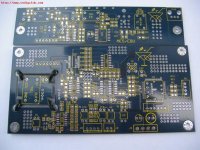
The photo I posted above is a FIFO/DDS solution for a CD transport done by a friend. Yep, it's for the transport output! You can put the same thing to the output side of transport, really. Unfortunately this board was done back in 2006, not available anymore. I also have another one which does the I2S. Again, it's long gone, too.
People around me dont pay much attention to this anymore because everybody is working hard on SDD/HDD player solutions. When you have a 1GB SRAM buffer, you can simply dump the whole CD into the buffer then read the data out with a low jitter clock.
This is why we did not do much on reclocking in D1V3. Simple reclocking cant do much good. Instead, we expect you to have a good digital source then the little DIR9001 will be just fine.
Oh, the PIC thing. It's similar to the Lavry solution, just much simpler. Again, the hardest part is not in coding the processor. 🙂
I'd suggest you start with Lavry's excellent white paper:
http://www.lavryengineering.com/white_papers/jitter.pdf
First you need a FIFO in adequate size. SPDIF will feed data to the FIFO, a stable clock is used to read data out of the FIFO. Since both clocks are running in different rates, you may run into the situation that the input data feeding is faster than the output reading or vice versa. What Lavry did is to use a CPU to monitor this data transmission trend. If the data is about to overflow, it will speed up the read clock. If the data is about to run out, it will slow down the read clock. The CPU does this job by feeding numbers to a 12bit DAC which in turns controls the frequency of a VCXO for reading clock. If you look at the output of this FIFO, you will see windows of data stream. Each window runs in a slightly different frequency but inside each window you have a fairly long stream of bit data in very low jitter.
The main challenge here is how to maintain the output linearity of the DAC hence good jitter performance of the VCXO. Not something can be easily done. Later people started to use DDS instead of this DAC/VCXO combo. You feed the new frequency number to the DDS then the chip will generate the clock for you with 2ps/rms jitter spec or even better.
When you talk about jitter reduction, you also have to consider the whole circuit, not just the XO itself. Every component will introduce extra jitter. This is why a crude PLL is of no good since it's a source of jitter itself already. The nice thing about FIFO/DDS is that the jitter performance is fairly consistently good and fairly predictable.
The photo I posted above is a FIFO/DDS solution for a CD transport done by a friend. Yep, it's for the transport output! You can put the same thing to the output side of transport, really. Unfortunately this board was done back in 2006, not available anymore. I also have another one which does the I2S. Again, it's long gone, too.
People around me dont pay much attention to this anymore because everybody is working hard on SDD/HDD player solutions. When you have a 1GB SRAM buffer, you can simply dump the whole CD into the buffer then read the data out with a low jitter clock.
This is why we did not do much on reclocking in D1V3. Simple reclocking cant do much good. Instead, we expect you to have a good digital source then the little DIR9001 will be just fine.
Oh, the PIC thing. It's similar to the Lavry solution, just much simpler. Again, the hardest part is not in coding the processor. 🙂
Basically it was determined that Lavry disabled his buffer on the DA-10 because it wouldn't work. See the DIYHIFI thread. Sounds like a great idea in the "white paper" but in practice it didn't work.
regal said:Basically it was determined that Lavry disabled his buffer on the DA-10 because it wouldn't work. See the DIYHIFI thread. Sounds like a great idea in the "white paper" but in practice it didn't work.
Or you should say that it's too expensive to do it right in a low end product like DA-10! 😀
Finney,
I've read most of Lavry's papers and I'm familiar with what he is doing. At this stage it's well ahead of my capabilities, and I want to get what I have up and running. That at least gives me some foundations I can build on.
I'm following roughly what Jos has sketched out: PIC -> 16bit serial dac -> Tent VCXO. I'm basically at the stage where I've got the PIC talking to the DAC via SPI, and have the comparator and PI loop running. The PI loop constants need tuning to get it to stabilize properly. When I posted earlier I'd been having some trouble with the SPI communication, but I have that sorted now.
I haven't done any PIC programming before, and it's a very long time since I did any programming of any kind so it's taking some time to get that sorted out. I've also put together a circuit I think should work reasonably well. It might not be perfect but I'm learning considerably more than if I simply buy someone's product.
cheers
Paul
Finney is right, I found their foreign lang forum thread talkin bout jitter elimination - long ago, with diagrams etc. Looking forward 2 solid state players!
FIFO/DDS solution for a CD transport
Finney,
There is something about "Removing CD drive jitter via buffering" on http://www.hydrogenaudio.org/forums/index.php?showtopic=54297
Isn't your above mentioned solution (in the Transport) goes the same direction that Genesis Technologies went with its Digital Lens, build by Paul McGowan, in 1996?
Putting it in the Transport (or just behind it), you get to the same problem as described in the Stereophile review
http://www.stereophile.com/digitalprocessors/824/
"The Lens suffers from one drawback inherent in all outboard jitter boxes: It must convert its jitter-free output into the S/PDIF or AES/EBU format to drive your digital processor. By putting the audio data back in S/PDIF, transmitting it down a cable, and recovering the clock with a PLL in your digital processor, jitter will be re-introduced. The jitter in your digital processor may be lower in amplitude and have a cleaner spectrum with the Lens, but it will still have some interface jitter as well as the intrinsic jitter of the digital processor's input receiver. Audio Alchemy's I2S bus alleviates this dilemma, but it works only with Audio Alchemy processors".
In other words: I have no idea how we should get clear stream for the D1V3 from a CD player, respectively.
Greetings,
IJ.
finneybear said:Hi Paul
The photo I posted above is a FIFO/DDS solution for a CD transport done by a friend. Yep, it's for the transport output! You can put the same thing to the output side of transport, really. Unfortunately this board was done back in 2006, not available anymore. I also have another one which does the I2S. Again, it's long gone, too.
............
This is why we did not do much on reclocking in D1V3. Simple reclocking cant do much good. Instead, we expect you to have a good digital source then the little DIR9001 will be just fine.
Finney,
There is something about "Removing CD drive jitter via buffering" on http://www.hydrogenaudio.org/forums/index.php?showtopic=54297
Isn't your above mentioned solution (in the Transport) goes the same direction that Genesis Technologies went with its Digital Lens, build by Paul McGowan, in 1996?
Putting it in the Transport (or just behind it), you get to the same problem as described in the Stereophile review
http://www.stereophile.com/digitalprocessors/824/
"The Lens suffers from one drawback inherent in all outboard jitter boxes: It must convert its jitter-free output into the S/PDIF or AES/EBU format to drive your digital processor. By putting the audio data back in S/PDIF, transmitting it down a cable, and recovering the clock with a PLL in your digital processor, jitter will be re-introduced. The jitter in your digital processor may be lower in amplitude and have a cleaner spectrum with the Lens, but it will still have some interface jitter as well as the intrinsic jitter of the digital processor's input receiver. Audio Alchemy's I2S bus alleviates this dilemma, but it works only with Audio Alchemy processors".
In other words: I have no idea how we should get clear stream for the D1V3 from a CD player, respectively.
Greetings,
IJ.
You could use a 74ct9046A PLL- VXCO to SRC before the SM5842.
That is if you don't want to be a pioneer with the buffer, could be a long and expensive ordeal.
Here is a diagram:
http://www.hagtech.com/pdf/hagdac.pdf
That is if you don't want to be a pioneer with the buffer, could be a long and expensive ordeal.
Here is a diagram:
http://www.hagtech.com/pdf/hagdac.pdf
simple, bypass the spdif receiver so the digital filter gets the i2s straight. Btw Finney also hinted something about a new transport with dsp onboard , can even bypass the digital filter then, sounds cool ? Anyway wadia has DSP upsampling since 80's, this might also "contribute something".
regal said:You could use a 74ct9046A PLL- VXCO to SRC before the SM5842.
That is if you don't want to be a pioneer with the buffer, could be a long and expensive ordeal.
Here is a diagram:
http://www.hagtech.com/pdf/hagdac.pdf
dear all
A decent (audio quality) PLL cannot be built with any of the xx46 PLL chips - avoid them
AVOID THEM !!!!!!!
best
finneybear said:IJ, why waste time and money on a crude PLL reclocking circuit driven by a mediocre XO?
IJ, Guido and I are talking about a total different subject.😀
finneybear said:Hi Paul
I'd suggest you start with Lavry's excellent white paper:
http://www.lavryengineering.com/white_papers/jitter.pdf
First you need a FIFO in adequate size. SPDIF will feed data to the FIFO, a stable clock is used to read data out of the FIFO. Since both clocks are running in different rates, you may run into the situation that the input data feeding is faster than the output reading or vice versa. What Lavry did is to use a CPU to monitor..............
You realy did not understand a word of Larvy's article.
 The used FIFO has nothing to do with the SPDIF signal. It has been used inside the PLL of a VCXO
 .
.- Status
- Not open for further replies.
- Home
- Source & Line
- Digital Line Level
- Real or fake PCM63?