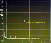
spzzzzkt said:from page 5 onwards there are spectrum analysis of various dithers. Only one has a flat noise floor.
Yes, the one without noise shaping... (TPDF dithering).
For measurements you should not use noise shaping. With only dithering, the noise floor is flat. 😎
spzzzzkt said:
The I/V used on the D1V3 is a modification of a Nelson Pass design and should have reasonable performance.
Look at
http://www.by-rutgers.nl/PDFiles/CD_eind.pdf
On the last page you will find the circuit. Use for the I/V-convertor a OPA314 and for the filter a OPA2314.
This is the best I/V-convertor I ever heard, designed by my friend Henk ten Pierick.
The connection between the DAC and the I/V must be as short as possible (within 2 cm). The 10 nF-condensor should be mounted on the DAC itself or left out.
PA0SU said:
Look at
http://www.by-rutgers.nl/PDFiles/CD_eind.pdf
On the last page you will find the circuit. Use for the I/V-convertor a OPA314 and for the filter a OPA2314.
This is the best I/V-convertor I ever heard, designed by my friend Henk ten Pierick.
The connection between the DAC and the I/V must be as short as possible (within 2 cm). The 10 nF-condensor should be mounted on the DAC itself or left out.
 opamp I/V?
 think I'll stick with the jfet I/V thanks.
spzzzzkt said:
think I'll stick with the jfet I/V thanks.
A semi conductor is a semi conductor mounted separately into a housing our mounted together with other semi conductors in a housing that forms an op amp. The techniques are equal. There is no rational reason to distrust op amps as long as you know which one to choose. The same counts for the choice of a 'single' JFET!
The OPA314 starts with JFETs, so....
The only question is: which JFET. The OPA314 seems to contain the right ones. Henk ten Pierick spended a great amount of money (he has bought about 40 different promising, sometimes very expensive, op amps), listened to them in a penel and developped thereupon a measuring method to rank them!!! It is no longer black magic to predict good audio. With his method he also ranks tubes !!!!!!!
Up till now, the OPA314 (OPA2314) is the best one for audio. Better than whatever circuit with discrete components.
PA0SU said:
A semi conductor is a semi conductor mounted separately into a housing our mounted together with other semi conductors in a housing that forms an op amp. The techniques are equal. There is no rational reason to distrust op amps as long as you know which one to choose. The same counts for the choice of a 'single' JFET!
The OPA314 starts with JFETs, so....
The only question is: which JFET. The OPA314 seems to contain the right ones. Henk ten Pierick spended a great amount of money (he has bought about 40 different promising, sometimes very expensive, op amps), listened to them in a penel and developped thereupon a measuring method to rank them!!! It is no longer black magic to predict good audio. With his method he also ranks tubes !!!!!!!
Up till now, the OPA314 (OPA2314) is the best one for audio. Better than whatever circuit with discrete components.
Herb,
diyaudio member jcx just wrote in a different thread some interesting information which challenge your comments. While being asked about comparing the OPA134 and OPA227, he wrote (http://www.diyaudio.com/forums/showthread.php?postid=1538795#post1538795 - Post #6) the following info:
"In a I out DAC I/V circuit there is an engineering case for preferring a fet input op amp. fet inputs can accept the fast steps and "glitch" energy of the DAC output with less input stage distortion compared to a similar GBW op amp with a hi gm bipolar input
but circuit topolgy can make a difference too - put a discrete or CFA buffer in the I/V loop on the output of the op amp to give low impedance at high frequencies and the feedback cap implementing the 1st pole of the reconstruction filter then "soaks up" some of the DAC's switching/glitch energy at frequencies where a single "audio" op amp's output impedance is high
the 227 has lower Vnoise and could be better in analog preamp stages where the signal doesn't have the high frequency steps of the DAC output
in spite of the above reasoning many DAC data sheet reference circuits use the bjt input 5534 in the I/V circuit with excellent measured performance #, so its the hardly the case that differences have to be "obvious" to the ear either".
(End of quotation)
Well, I hope this will help a bit. Otherwise I can't see how you and Paul are going to agree about anything, at least not anytime soon 😉
IJ.
irgendjemand said:"In a I out DAC I/V circuit there is an engineering case for preferring a fet input op amp. fet inputs can accept the fast steps and "glitch" energy of the DAC output with less input stage distortion compared to a similar GBW op amp with a hi gm bipolar input
OK, (I did not say any thing about this!)
but circuit topolgy can make a difference too - put a discrete or CFA buffer in the I/V loop on the output of the op amp to give low impedance at high frequencies and the feedback cap implementing the 1st pole of the reconstruction filter then "soaks up" some of the DAC's switching/glitch energy at frequencies where a single "audio" op amp's output impedance is high
mind that the output impedance of the DAC is high. It is a so called current source !!!!!!!!!!! But, there could be some cross talk. Therefore serves the 10 nF capacitor in my circuit diagram.
than what?the 227 has lower Vnoise
I prefere the OPA314 !and could be better in analog preamp stages where the signal doesn't have the high frequency steps of the DAC output
with an inadequate measuring method !!in spite of the above reasoning many DAC data sheet reference circuits use the bjt input 5534 in the I/V circuit with excellent measured performance #,
so its the hardly the case that differences have to be "obvious" to the ear either".
I left the 5534 behind me already for many years. Many people take the 5534 synonym for 'op amp'. However, the op amp world is larger than the 5534..................
There are many ways to skin a cat in audio design. You don't gain much respect by loudly proclaiming you know the only acceptable way to perform the task.
spzzzzkt said:There are many ways to skin a cat in audio design. You don't gain much respect by loudly proclaiming you know the only acceptable way to perform the task.
Bernhard said:No op amps, transistors or tubes. No trouble.
Sleep well.😱 😱 😱
Ok, just got email from Spencer about this thread. I have been away for a while, been busy with moving, etc.
Regarding to the differences among K, K2, KY, and Y grades of PCM63, well, the reality is nobody knows the exact answer. The info I have gathered so far are:
1. PCM63 was first made in the U.S. The US made K is still considered among the best of the best.
2. The part sorting criteria for K grade is in fact quite loose. Definitely you can pick better ones among K parts. I know one guy bought up a batch of Korea made Ks, picked out the lowest noise ones then dumped the rest cheap over the net.
3. Obviously Sony signed up a contract with BB for K2 chips. Those K2 chips were used on professional machines such as PCM-3348HR (later HR switched PCM1702), etc. A diyer did a test on K, K2, and KY. K2 consistently has lower noises. Listening test also shows K2 has better extension on both top and bottom ends.
4. It's very easy to recognize those Sony K2 chips. They all have a red band across the top of the chip. Almost all K2s were made in Japan. Some reported K2s packaged in Philipine.
5. Similarly, Yamaha got special parts from BB. Those are KY chips. Some feel they sound more *musical* than plain K.
6. Y grade seems to show up a bit later than K2 and KY. Listening test says it has the best part of K2 and KY. This is for early, Japanese made, Y chips though, not those with laser etched Y mark.
7. Y grade is mostly for pro machines as well.
8. PCM63 enjoyed a fairly long production history. Along with the improvement of yield and manufacturing techniques, definitely you would get a lot of above-K grade parts near the end of production run. This may be the reason why we would see so many late production Ys marked in different ways. Sure, this also means the chance of getting fake Y is very high.
-finney
PA0SU said:A semi conductor is a semi conductor mounted separately into a housing our mounted together with other semi conductors in a housing that forms an op amp. The techniques are equal. There is no rational reason to distrust op amps as long as you know which one to choose. The same counts for the choice of a 'single' JFET!
Nope. The problem with OP amp is exactly that an OP has multiple FETs and transistors inside. It also has resistors, capacitors, etc, made in silicon inside. Everything is done through doping, etching, etc, so part matching is an issue, the performance characteristic is much less than ideal (especially true for capacitors).
Sure, you also have some advantages here such as most transistors on the same die have the same temperature coefficient hence make certain circuit topology possible.
To make everything simple - OP amp circuit design is very different from circuit designed with discrete parts.
Even when certain technique such as laser trimming is available, part machting still is a big problem for OPs. Manufacturers have been working diligently to find out new processing and design tricks to produce higher quality parts. LM4562 is one of the latest examples.
The only interrest we have is: are the differences relevant to us DIY-ers? I think not. Sea my posting 356.finneybear said:Regarding to the differences among K, K2, KY, and Y grades of PCM63, well, the reality is nobody knows the exact answer.
-finney
Do'nt treat all the integration 'problems' equal. Were we are talking about audio frequencies. Stick to this and develop the best method to choose, as Henk ten Pierick did.Nope. The problem with OP amp is exactly that an OP has multiple FETs and transistors inside. It also has resistors, capacitors, etc, made in silicon inside. Everything is done through doping, etching, etc, so part matching is an issue, the performance characteristic is much less than ideal (especially true for capacitors).
We are not talking about op amps with a G.B of 1 GHz. For our applications all your objections are of no interrest.
Not only the temperature but all the other parameters too.Sure, you also have some advantages here such as most transistors on the same die have the same temperature coefficient hence make certain circuit topology possible.
No, No, NO!!! One of the great advantages of integration is that the properties of the integrated components are equal, not in absolute value but compared to each other, so it became possible to build long tail pairs, current mirrors, etc. etc.Even when certain technique such as laser trimming is available, part machting still is a big problem.
For rather simple applications as audio, trimming is out of the question. Only in special cases where absolute values of eg. resistors should be obtained, trimming comes in sight.
Sure, sure, sure, but the subject here is: are there fake PCM63's, whatever this should mean.finneybear said:BTW, there are also PCM-1704 K, 2K, and 3K chips! Man, do we have fun here? 😉
PAOSU,
in post 356, my major concern is that your statment may misslead others on whether the chips is real or fake. Since there is no proof that and no evidence to tell how BB sort the parts and we are here to share experience and ideas to real or fake chips. A statement as below would be quite misleading!
There is no any correlation between distortion and the type Y or K, so the Y's are no fake !!!
I would alter the statement to be:
There is no any correlation between distortion and the type Y or K, so the Y's are no real !!!
There is no absolute right or wrong here as the chips you are looking is not same chips as those others diyer are testing.
Spencer
Those who got chance to read this document understand why op-amp will not sound very good as I/V and understand why NP D1 I/V sound better.
due to copyright issue and I shall not send the doc to others. Please buy from AES.
due to copyright issue and I shall not send the doc to others. Please buy from AES.
Attachments

no need to share it once again, its here:
http://www.essex.ac.uk/dces/researc...Current steering transimpedance amplifier.pdf
http://www.essex.ac.uk/dces/research/audio_lab/malcolms_publications.html
http://www.essex.ac.uk/dces/researc...Current steering transimpedance amplifier.pdf
http://www.essex.ac.uk/dces/research/audio_lab/malcolms_publications.html
PA0SU said:The only interrest we have is: are the differences relevant to us DIY-ers? I think not. Sea my posting 356.
The answer is definitely yes. I can hear the differences between K, K2, and KY. Many other can hear those, too. Whether can you hear it? Well, first you will have to see whether your DAC is good enough to hear the difference. 😉
Do'nt treat all the integration 'problems' equal. Were we are talking about audio frequencies. Stick to this and develop the best method to choose, as Henk ten Pierick did.
We are not talking about op amps with a G.B of 1 GHz. For our applications all your objections are of no interrest.
Audio frequency? Dont play word game here. What's your definition of audio frequency? We all know that I/V does not work just in 20-20KHz. Enough said.
1GHz? Most OPs even do not have a gain bandwidth as high as 1GHz. Tell OP makers that those are non-issues for OPs with GB less than 1GHz. 😉
Not only the temperature but all the other parameters too.
You are playing word game here again. Surely there are other stuff involved. I was just giving out temperature coefficient as one example.
No, No, NO!!! One of the great advantages of integration is that the properties of the integrated components are equal, not in absolute value but compared to each other, so it became possible to build long tail pairs, current mirrors, etc. etc.
Obviously you know none, or very best, little of IC fabrication. The problem exactly lies in the integration itself! Most parts etched on the substrate are simply not equal! No wonder you would say laser trimming is only for critical application.
If you were talking about those Apex parts then it would be a wholly different story. That's real integration.
For rather simple applications as audio, trimming is out of the question. Only in special cases where absolute values of eg. resistors should be obtained, trimming comes in sight.
Again, you are missing the mark. Laser trimming is good and is important. OP makers do not apply it to every OP mainly because of the cost.
Audio application has never been simple. Based on your view, National Semi must be very dumb to spend so much effort/money on bringing out LM4562 mainly for audio application? I will tell your statement to Bob Pease when I run into him next time. I am sure he'd love to discuss this with you. Hehe
Sure, sure, sure, but the subject here is: are there fake PCM63's, whatever this should mean.
Probably this will disappoint you again. Yes, people can hear big differences among PCM-1704K, 2K, and 3K. As for fake PCM-63K, K2, and KY. Well, after you have heard what geniue ones can do for you. You will know how to recognize fakes. 😉
-finney
flshzug said:no need to share it once again, its here:
http://www.essex.ac.uk/dces/researc...Current steering transimpedance amplifier.pdf
http://www.essex.ac.uk/dces/research/audio_lab/malcolms_publications.html
I am afraid that for those only care about 20-20KHz, they will never understand this paper. But again, this paper even had not touched the problems encountered in real world parts such as the input noise issue in current feedback OPs, and the input impedance curve change before OPs output has settled down. Experiences tell me that the later is one major sonic killer. This is especially true for modern DAC chips with high modulation frequency.
-finney
spencer said:A statement as below would be quite misleading!
There is no any correlation between distortion and the type Y or K, so the Y's are no fake !!!
I would alter the statement to be:
There is no any correlation between distortion and the type Y or K, so the Y's are no real !!!
There is no absolute right or wrong here as the chips you are looking is not same chips as those others diyer are testing.
Dear Spencer, I realy do'nt know what you mean. The word 'fake' includes criminal activities as my dictionary does not fake me.
Another exemple: Volkswagen stopped production of its Beetle many years ago. At that time the Beetle has been fabricated in South America (I forgot the country). Is that Beetle a fake? NO. Volkswagen sold the rights. The same counts for the PCM63.
What do you mean by:
'not the same chips as those others diyers are testing' ?
(or without the errors in English:
not the same chips as those which other diyers have been tested.)
Is my K another K then yours? Is my Y different from any other Y?
- Status
- Not open for further replies.
- Home
- Source & Line
- Digital Line Level
- Real or fake PCM63?