irgendjemand said:I do remember you swapping PCMs between 2 devices, etc. What I am still not sure about is if you did found any matched-pair of Y‘s, either by measurements nor by listening.
I swapped the K's in my CD624 with those in the TentDAC and listened to the two systems, and I can not here any difference.
With the Y's of A'af I did measurements. I could find only one Y which measured better than my K's. I'm waiting for a new emission from A'af......
Remember: I do not believe so mutch in the great differencies folks are talking about AFTER RECLOCKING as I stated before, but as soon as I received the other Y's (or what ever) from A'af I will arange a pennel-meeting and do some listening tests.
P.S.: In my CD624, a combination of one of my best K's with the one Y which measured best, did not give any audio difference.😕
PA0SU said:(...) as soon as I received the other Y's (or what ever) from A'af I will arange a pennel-meeting and do some listening tests.
P.S.: In my CD624, a combination of one of my best K's with the one Y which measured best, did not give any audio difference.😕
Herb, one possibility is to temporary re-build 2 PCM's sockets in my AVM DAC, so that we will be able to listen to the differences between best Y's and best K's as I experienced.
AFTER WHICH we (you 😉 ) will build in my DAC the reclocking device and we will listen again. In this way, we will surely come to the answer.
It will be extremely interesting test. At first – we will hear differences in selection's grade (I promise…) but having no more differences after your reclocking will be something!.
Meanwhile I assume that this thread will fall asleep for a while, at least until you will get the second best measured “Y from A’AF. Hope we can come to it sometime soon. Also many thanks in advance.
p.s Am still looking for the DAC plan.
irgendjemand said:
Herb, one possibility is to temporary re-build 2 PCM's sockets in my AVM DAC, so that we will be able to listen to the differences between best Y's and best K's as I experienced.
is not so easy, but I could dispose of special tools for this job
AFTER WHICH we (you 😉 ) will build in my DAC the reclocking device and we will listen again. In this way, we will surely come to the answer.
Before we do something or traval around with the equipment, I need diagrams of the DAC in qusetion.
As far as I can see the only way to get a reasonable idea of how the Y's perform compared with the datasheet specs is to replicate the testing done by BB as far as possible.
According to the datasheet the tests were made with OPA27 opamp and 1.5Kohm resistor in the feedback possition. This was then feed into an programable gain amplifier and passed onto a THD meter with bandwidth set to 400hz -30Khz.
I'm in the process of putting together a Tangent designed Low noise measurement preamp (LNMP) with 60dB gain that should stand in for the programable gain amplifier. I've also just received a couple of OP27 (not quite the same but close) opamps and I'll make up an adapter board to feed the PCM63P output into the OP27 I/V and bypass the jfet I/V on the D1V3.
The Audiofire2 has spdif output so I'll be also able to eliminate the influence of the CD/R induced distortion by feeding the DAC directly. Signals on CDR are not of the same quality as commercial test CD's - try viewing the eye pattern resulting from playing a CDR sometime and you'll understand why.
The THD measurements are more problematic. I'm still waiting on the Audiofire2 interface, but at this stage the plan is to record output of the LNMP using the Audiofire2.
spzzzzkt said:
The Audiofire2 has spdif output so I'll be also able to eliminate the influence of the CD/R induced distortion by feeding the DAC directly.
I do not understand you.... which is the indirect way?
Signals on CDR are not of the same quality as commercial test CD's - try viewing the eye pattern resulting from playing a CDR sometime and you'll understand why.
The quality of digital signals is defined by the quality of the signal which leaves the decoder of the transport. If the transport is quite well, also signals with a bad eye-patern will be read correctly. The only thing you have to do is: look if there are reading errors. The decoder reports this.
If there are errors, nothing between the decoder and the DAC under test, can enhance the digital quality any more, so I realy do not know what you mean....

Digital systems are transparant.
- Test Tone -> CDR-> CD Transport -> SPDIF -> DAC
- see cdr tests here: http://members.chello.nl/~m.heijligers/DAChtml/jittermeas/jitter.html
- see cdr tests here: http://members.chello.nl/~m.heijligers/DAChtml/jittermeas/jitter.html
spzzzzkt said:- Test Tone -> CDR-> CD Transport -> SPDIF -> DAC
This is your 'direct way' as I understood it well, but what is the indirect way?
What do you mean by 'Test Tone? A digital generated tone from an audio edtor?
- see cdr tests here: http://members.chello.nl/~m.heijligers/DAChtml/jittermeas/jitter.html
This is a entire different subject !
I'm using Wave Editor http://www.audiofile-engineering.com/waveeditor/ to generate test tones at 32bit, then dithering down to 16bit using the Izotope MBIT+ dither function. This is exactly the same type of file I've been burning to CDR. The MBIT+ dither might not be the best choice as the developers claim it is optimised for music, rather than test tones.
The more direct method is actually Wave Editor -> Audio Interface -> SPDIF -> DAC, not Wave Editor -> CDR -> Transport -> SPDIF -> DAC.
Eye pattern is a indicator of quality of recovered signal, and cd-r have clearly degraded eye pattern compared with commercial cds. Hook up an oscilloscope to your transport's RF testpoint and this plain to see. Oddly enough there is a measurable difference in the distortion of the same test signal recorded to different CDR's if the tests referred to above are any guide.
I'm trying to eliminate these variables as far as possible. Ideally a commercial test cd would be the way to go, but I needed a decent audio interface for the laptop so digital test tone to spdif is how I'm planning to proceed.
spzzzzkt said:
Eye pattern is a indicator of quality of recovered signal, and cd-r have clearly degraded eye pattern compared with commercial cds. Hook up an oscilloscope to your transport's RF testpoint and this plain to see. Oddly enough there is a measurable difference in the distortion of the same test signal recorded to different CDR's if the tests referred to above are any guide.
As long as the decoder in the transport does not report read errors, the quality is perfect.
I'm trying to eliminate these variables as far as possible. Ideally a commercial test cd would be the way to go, but I needed a decent audio interface for the laptop so digital test tone to spdif is how I'm planning to proceed.
I have a PC-card running under Win98 (NOT XP) with an ISA-slot-connection, so very old fashioned..... This card gives AES/EBU input and output. I think that there schould be an interface card for laptop. DO NOT USE USB !!!
flshzug said:what card is that? The original Prism Dscope ?
No, a MULTI!WAV DIGITAL 'the ultimate direct digital transfer card for Windows'.
Google-hits:
http://www.jstor.org/pss/3681053
http://www.geocities.com/multiwav/multiwavdriversandsoftware.htm
As you could read there, it is an old fashioned card from 1995 or earlier.
It is an excellent card for those days.
By the way, it is for sale.....
PCM63 K's and Y's compared......
For the comparison I generated me a test disk with 991 Hz-signals of -78 dB up to 0 dB in 6 dB-steps. Measuring only at 0 dB and -60 dB is absolutely insufficient. Some IC's are excellent with -60 dB and very bad at -66 dB or -54 dB. Be careful!
Thanks to A'af, I could test 14 PCM63 K's and Y's with this disk. I counted the harmonics which were 3 dB over the noise floor with each step and added them finaly.
There is one K and one Y which showed no more than 15 harmonics over the noise floor in the 16 measuring levels. These are the best ones.
The worst one was a Y with 76 peaks!
There is no any correlation between distortion and the type Y or K, so the Y's are no fake !!!
Some K's are dated 1994, some 1993. All Y's are from 2004.
Did the best IC's sound better than the bad ones? Hardly.
As soon as the harmonics peaked over the noise, the THD was always better than 0.02 %. In the very most cases 0.01 % or better.
The interface I purchased uses firewire to connect to laptop and has a coax spdif in and out, plus balanced audio in and out.
Running the test signals from the laptop certainly makes testing a bit easier, but I can't say that the results are significantly better. I haven't had time to build up an adapter board for the chips and so using the I/V output the test results look similar to those done using the HDP2 minus some of the low level junk.
After inital testing showed that the highest harmonic peaks were at the same levels as in previous tests I moved on to comparing rms level of the recorded signal, with the rms of the same file with 997hz notch filter, 400hz high pass and 14khz low pass. The 14khz low pass was used to remove the rising noise floor of the dither. Hopefully this method gives a reasonable approximation of the spec sheet THD + N at -60dB figures.
The above testing methodology was about as close as I could get to the original BB setup. I'd note that the BB testbed of opamp I/V -> low noise preamp -> filter -> thd meter should add significantly less noise/distortion than my rig of discrete I/V and buffer -> sound card electronics and A/D conversion -> Wave Editor -> apEQ filtering plugin.
The results were fairly close across the chips I tested. The worst chip had a THD + N of 37.4dB, whilst the best was 39dB. This falls within the range of factory spec values for the PCM63P. Given the handicap of my test setup, this would suggest testing in a similar rig to the factory setup the best of the chips would be of at least PCM63P-J and possibly PCM63P-K grading.
I also measured two of the PCM63K chips I have and the best of these measured very close to several of the better Y marked chips.
So best of these chips do seem to measure up to borderline PCM63P-J grading even suffering under the handicap of being run through a A/D convertors a of mid level soundcard. Given a setup that replicated the BB rig I'd expect that they would measure close to K grade.
spzzzzkt said:
The 14khz low pass was used to remove the rising noise floor of the dither.
I'd note that the BB testbed of opamp I/V -> low noise preamp -> filter -> thd meter should add significantly less noise/distortion than my rig of discrete I/V and buffer -> sound card electronics and A/D conversion -> Wave Editor -> apEQ filtering plugin.
The worst chip had a THD + N of 37.4dB, whilst the best was 39dB. This falls within the range of factory spec values for the PCM63P.
The rising noise floor of the dither ?? I never noticed this. (Look at the pictures above).
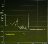
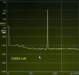
For me, the only way to test a DAC is in combination with the I/V-convertor. Otherwise you should measure the output current of the DAC. (Be aware that the input-impedance of the circuit behind the PCM63 should be low! With my I/V this is less than 1 ohm because of the virtual ground.)
It is not so difficult to build a very good I/V-convertor + low pass at 20 kHz with 12 dB/oct without any capacitor in the signal-path and with less than 100 uV DC at the output. You could find one on my web site (the explanation is in Dutch, sorry!).
For the measurements I use a CLIO-system from Adiomatica: a special sound card + special software for measuring loadspeker systems. One of the options is FFT. The noise floor of this system is -130 dB. If I play a track with 'silence', the noise level is also -130 dB, so the I/V and the power supply are OK. If I start a track with, say, -90 dB than the noise floor rises to -113 dB with an I/V-convertor which outputs 8 dB more than the red book prescribes (0 dB is with my set up +8 dB on the analyser).
I also generated a CD with a 'log. fade in' from -96 dB to 0 dB over a time range of 10 min. Watching the analyser with this test signal is very instructive.

PA0SU said:
The rising noise floor of the dither ?? I never noticed this. (Look at the pictures above).
http://www.google.com/search?q=shaped+noise+dither
I made an observation that my test setup was significantly different to BB and there for test results were different. The I/V used on the D1V3 is a modification of a Nelson Pass design and should have reasonable performance.
better than wading thru google results:
http://audio.rightmark.org/lukin/dither/dither.pdf
from page 5 onwards there are spectrum analysis of various dithers. Only one has a flat noise floor.
http://audio.rightmark.org/lukin/dither/dither.pdf
from page 5 onwards there are spectrum analysis of various dithers. Only one has a flat noise floor.
- Status
- Not open for further replies.
- Home
- Source & Line
- Digital Line Level
- Real or fake PCM63?