Not sure what your question is “what about soldering?”
The board will be produced and I will individually test it to make sure it works before shipping it. You need to solder your choice of speaker and amp connectors: through hole parts with spade or Molex quick connects. The 2 pin JST connector for power will be pre-soldered.
The board will be produced and I will individually test it to make sure it works before shipping it. You need to solder your choice of speaker and amp connectors: through hole parts with spade or Molex quick connects. The 2 pin JST connector for power will be pre-soldered.
More good news then X, I was going to ask you about final testing - you have answered that question in the previous post.
The sample provided was probably hand soldered. The final production will be solder paste via stencil and an automated pick and place machine with automatic reflow ovens. I would assume it will look professionally made - if you are wondering if it looks like the sample sent. Despite the looks - it worked fine.
I am sure they would most likely have hand soldered a one off sample rather than program the PNP for 1 board (especially a small pcb like this one) - anyway wait and see if the production run looks a lot better when it comes to the soldering quality.
X, so you will be fitting the 2 way H101 connector, as mentioned in a previous post. Are the X105 and X115 molex connectors the same as used on the SLB pcb's?
X, so you will be fitting the 2 way H101 connector, as mentioned in a previous post. Are the X105 and X115 molex connectors the same as used on the SLB pcb's?
Last edited:
X, so you will be fitting the 2 way H101 connector, as mentioned in a previous post. Are the X105 and X115 molex connectors the same as used on the SLB pcb's?
Yes and yes.

Hi again X,
Do you have a Mouser part number for the 2 pole connector that will mate with the H101 connector you will solder to the pcb. Also a part number for the female pins to suit would be handy, thanks.
For those other forum members getting these assembled pcb's and who want to use the molex connectors for speaker and amp connections to the board (not supplied with the assembled pcb), the Mouser part numbers are:
4 pole right angle header = 538-26-01-3115
4 pole housing to match the header = 538-39-01-2040
female crimp pin = 538-39-00-0039
regards,
Gary..
I plan on installing these Molex KK series 2-pin 2.54mm pitch PCB mounted header pin connector part no 22-27-2021:
22-27-2021 Molex | Mouser
I think these are the matching KK crimp contacts, part no 08-50-0032:
08-50-0032 Molex | Mouser
And these are the mating Molex KK 2 pin sockets part no 22-01-3027:
22-01-3027 Molex | Mouser
Also note that standard TE Connectivity spade connectors can also be fitted to the amplifier input and speaker output terminals instead of the Molex quick releases.
Last edited:
Thanks for that info X, appreciate it, hopefully will be handy for other members as well.
That leads me to a couple of more questions.
1. Do you have a simple wiring diagram to help wire up these 3 connectors (for those using them) showing which channel plus and and gnd connect to on the 4 pole molex connectors and the supply polarity on the 2 pin connector you are installing.
2. Also, I assume one of these SSR boards will handle both channels for a stereo amp chassis build.
3. I think I read that the power for the SSR pcb can be derived from the amp positive rail and GND. What are the min and max values for the DC supply for this board.
4. Also can it be powered from a separate supply - that is , it does not need to be referenced to the amp supply for the amp it is protecting.
5. It might be wise to supply a wiring diagram with each pcb you sell so members get them installed and wired correctly from the outset.
Regards,
Gary..
1. Do you have a simple wiring diagram to help wire up these 3 connectors (for those using them) showing which channel plus and and gnd connect to on the 4 pole molex connectors and the supply polarity on the 2 pin connector you are installing.
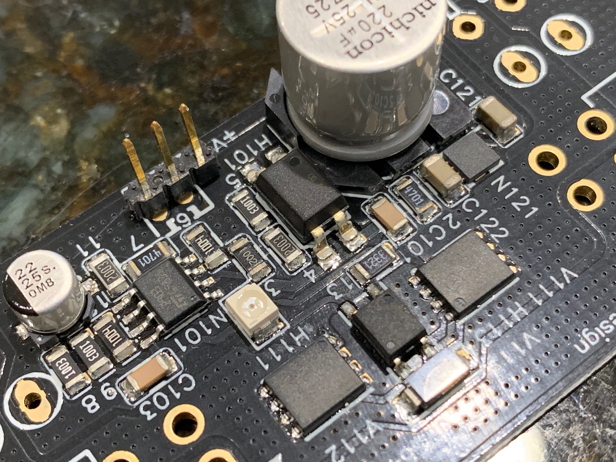
The top row of pins is GND, the lower row is Amp input + on left, and Speaker + on the right side. The +V input is on the left pin of the Molex connector, right pin is GND.

2. Also, I assume one of these SSR boards will handle both channels for a stereo amp chassis build.
No, it has been clearly stated early on that these are mono, 1 board per channel.
3. I think I read that the power for the SSR pcb can be derived from the amp positive rail and GND. What are the min and max values for the DC supply for this board.
Minimum would be about +18v, max value that we recommend is +50v. The on board voltage regulator can handle 150v, so no issue there.
4. Also can it be powered from a separate supply - that is , it does not need to be referenced to the amp supply for the amp it is protecting.
That's correct, a 19v or 24v volt supply from a wall wart would be fine.
5. It might be wise to supply a wiring diagram with each pcb you sell so members get them installed and wired correctly from the outset.
That's what the thread is for, but a good idea to make it more idiot-proof. It's hard to mess up the connections.
The top row of pins is GND, the lower row is Amp input + on left, and Speaker + on the right side. The +V input is on the left pin of the Molex connector, right pin is GND.
2. Also, I assume one of these SSR boards will handle both channels for a stereo amp chassis build.
No, it has been clearly stated early on that these are mono, 1 board per channel.
3. I think I read that the power for the SSR pcb can be derived from the amp positive rail and GND. What are the min and max values for the DC supply for this board.
Minimum would be about +18v, max value that we recommend is +50v. The on board voltage regulator can handle 150v, so no issue there.
4. Also can it be powered from a separate supply - that is , it does not need to be referenced to the amp supply for the amp it is protecting.
That's correct, a 19v or 24v volt supply from a wall wart would be fine.
5. It might be wise to supply a wiring diagram with each pcb you sell so members get them installed and wired correctly from the outset.
That's what the thread is for, but a good idea to make it more idiot-proof. It's hard to mess up the connections.
Attachments
To elaborate a little bit, the supply voltage common (GND) is electrically connected to the common (low side) amp/speaker connection.
I'm sorry, but I am a bit confused with the connections.
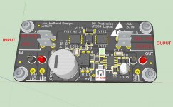
I can understand the two QC connectors for leads from the amp on the left, and two similar QC for leads to the speaker on the right, in your 3D model image above. But the connectors at the bottom of the image, lower-power ones, are confusing me. I understand that some sort of DC supply will be connecting to some of those leads, but there seem to be more connectors than necessary just for the DC supply. There is an "in" and "gnd" on the bottom left, and a "v+", "gnd" and an "out" on the bottom right.
I am guessing that the 2-pin Molex on "v+" and "gnd" is for the DC supply. The other three are for....?
Please help?
Last edited:
The leftmost connections marked GND and IN are redundant with the QC inputs so you could use right angle pins there to plug the board into a mother board. Same is true for the connection on the lower right side of the board marked OUT. The footprint in the lower middle where local power is supplied happens to be three pins with V+ (positive) in the middle and V- (GND) on either side. You only need to connect to two of those three, as is done with the header shown in the picture.
Understood. Thanks. I guess I'll get a clearer picture once I receive the boards and check continuity of a few points. 🙂
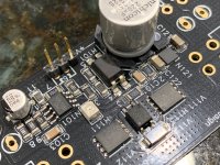
Good news folks, we just got word that the full production run of 120 units has been completed!
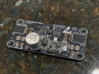
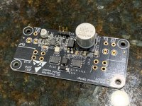
Also, I received the 1st unit sample that they sent Jhofland to test. It looks much nicer in person compared to the grainy photo that they sent. Here are some nicer high resolution photos of the sample unit. I hooked it up to my VHEX+ amp and it works well. I even made a video of how easy it is to install. I will have to see how to best post the video (might have to be on the IG account... TBD).


Also, I received the 1st unit sample that they sent Jhofland to test. It looks much nicer in person compared to the grainy photo that they sent. Here are some nicer high resolution photos of the sample unit. I hooked it up to my VHEX+ amp and it works well. I even made a video of how easy it is to install. I will have to see how to best post the video (might have to be on the IG account... TBD).
Attachments
- Home
- Group Buys
- Ready-to-Run (RTR) SSR DC Speaker Protection and Delay GB