Nice work, Vunce! I see you are living dangerously - flying lead direct solder to the SSR board from the amp and speaker connector.
What’s the Meanwell 5v SMPS for?
What’s the Meanwell 5v SMPS for?
Haha!! I know right 😉
The SSR DC protection boards are not going anywhere, so I kept hookup low profile 😀
The 5V Meanwell is to enable the Cresnet SMPS to enter standby mode. The front panel power switch turns the Meanwell On/Off.
The SSR DC protection boards are not going anywhere, so I kept hookup low profile 😀
The 5V Meanwell is to enable the Cresnet SMPS to enter standby mode. The front panel power switch turns the Meanwell On/Off.
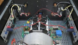
That’s a nice looking amp, Drpro! Very clean neat and tidy implementation. I like how you mounted those RTR SSR’s.

Great news folks: the second batch of SSR’s is finally shipping out today from the board assembly house!
Thanks for the renewed interest in these items - just got a few more orders since I announced the shipments were on their way.
As much as I want this circuit, unfortunately I have bridge tied load (BTL) amps (monoblocks) where both speaker outputs are live. Is there a workaround for this?
Let’s ask Jhofland. I know that he changed gen 2 to have the board’s ground isolated from the amp outputs. I think the problem may be where we are looking at DC from.
This version of the circuit ties the speaker low side to common (ground) and shares that connection with the power used for the board so fault sensing is between the amp output and that common. Connecting it to a bridge tied output will work if, and only if, the DC level of the output is zero relative to common. It will also require using a protection circuit on both outputs.
The fix is pretty simple schematically. Separate the sensing so it is between amplifier hot and amplifier cold and is independent of the supply common. This can be done because the sensing is done optically, and is what I have done in the next generation of the circuit. The side benefit is that it only requires one protection circuit for a bridge tied load. I have not looked at the layout of the existing design with respect to the difficulty of separating common and the amp cold output and still maintaining the correct connection to the sensing circuit.
The fix is pretty simple schematically. Separate the sensing so it is between amplifier hot and amplifier cold and is independent of the supply common. This can be done because the sensing is done optically, and is what I have done in the next generation of the circuit. The side benefit is that it only requires one protection circuit for a bridge tied load. I have not looked at the layout of the existing design with respect to the difficulty of separating common and the amp cold output and still maintaining the correct connection to the sensing circuit.
I wonder if there is a surgical fix by cutting a trace and adding a small jumper? Except for Class D BTL amps, I think most Class AB BTL amps have 0v DC at either output - that can easily be be verified by the user with a DVM.
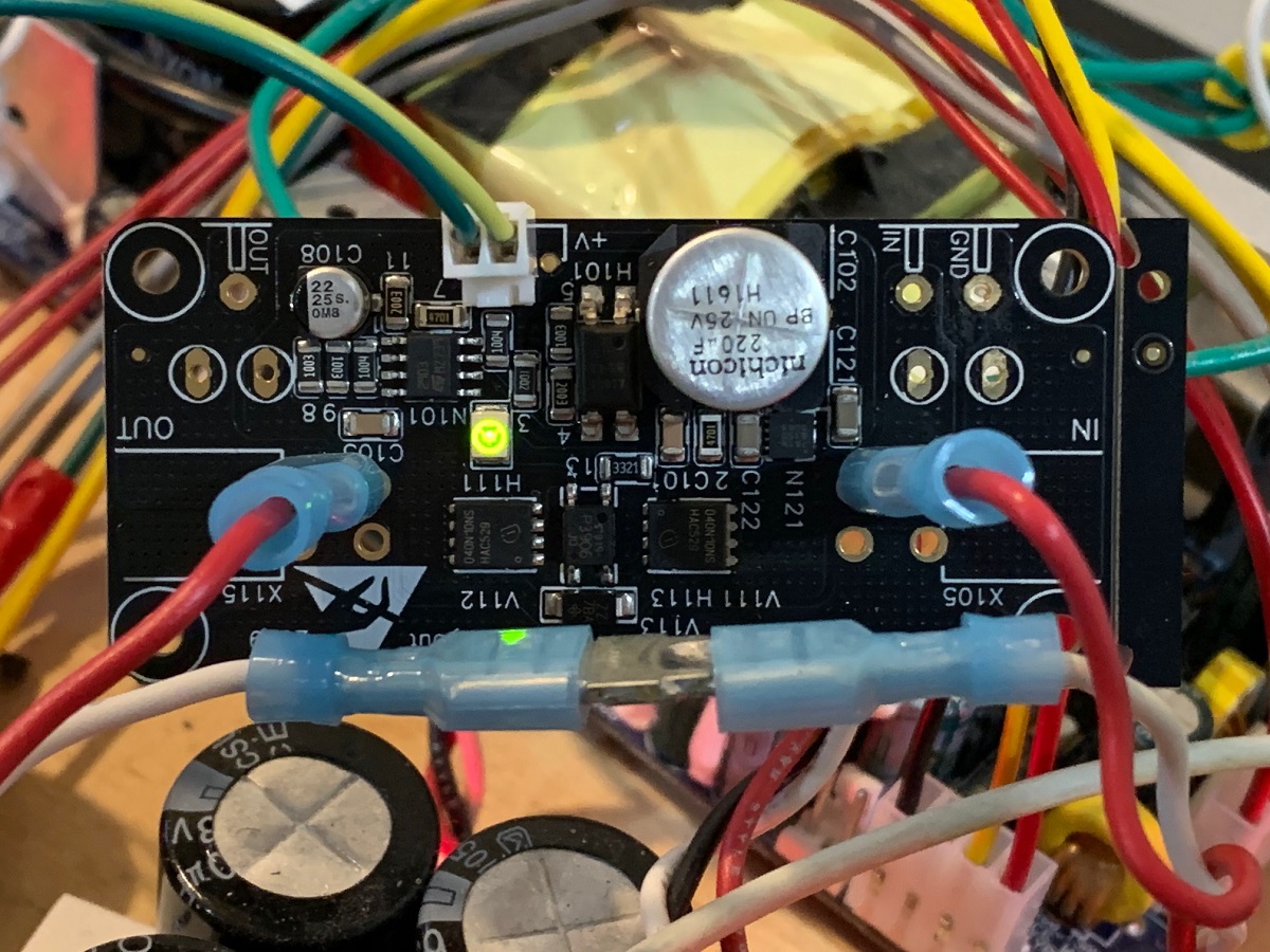
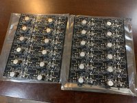
The new GB 2 boards are in. I tested a few random samples and they work. So now I need to install the 2 pin Molex KK connectors and test each one in my amp to make sure music plays. Then they can be shipped out. They are looking good though.
Just unsealed from their ESD safe bags:

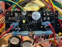
Testing with my amp:
Just unsealed from their ESD safe bags:
Testing with my amp:
Attachments
I just finished testing 30 units and they all checked out. Need to package them up and then ship out. Just realized that I am out of bubble mailer envelopes.
ceramic pads
Hello X
I have ordered 2 ssr's from your Etsy shop.
Could you possibly include 8 or even better 12 ceramic pads 1 mm thick to be used with TO-247 or TO-3PN-3.
One fits all ?
If so, please let me know how to pay for them.
Hello X
I have ordered 2 ssr's from your Etsy shop.
Could you possibly include 8 or even better 12 ceramic pads 1 mm thick to be used with TO-247 or TO-3PN-3.
One fits all ?
If so, please let me know how to pay for them.
My order of bubble mailer envelopes arrived so I will start packaging and sending the SSR orders our over next couple of days. Thanks for everyone’s patience.
All of the RTR SSR’s have been tested, packaged and sent out. These take a lot of time to package as they are wrapped with blue tape and foam spacers. Then covered with a cardboard shield, then placed inside a bubble mailer which is then armored with extra packaging tape. I used the same method last time on GB1 and they all arrived safely and in working condition. But I ended spending like 5hrs packaging everything and putting shipping labels on all of the orders.
I do like to hear from folks when you implement these RTR SSR’s. Please share your installation or application when you end up using them.
Thanks,
X
I do like to hear from folks when you implement these RTR SSR’s. Please share your installation or application when you end up using them.
Thanks,
X
Last edited:
- Home
- Group Buys
- Ready-to-Run (RTR) SSR DC Speaker Protection and Delay GB