According to manual: "PCM Clock Modefor me it would need to be able to handle 90.3168/98.304MHz, while leaving the ESS OSF enabled. unless I use some sort of multiplier.
I think even with fifo we need to make sure its an audio frequency clock rate, the fifo will do what it can, but cant reverse aliasing
0 = Master mode. The PCM CLK is an output
and drives at the MCLK rate."
The question is how MCLK can be set - I didn't find this in the BCM2385 ARM peripherals.pdf
KOON3876, do you know something about how the PCM_MCLK frequency is set?
Raspberry Pi • View topic - I2S: Anyone got it running?
Gert is talking about CLOCK control at this thread, but for internal clocks.
I want to supply MCLK (bit clock) from outside.
When I want to process 176.4kHz,
45.158MHz xtal -> as Master Clock, for DAC
45.158MHz -> HC163 counter -> 1/4 output = 11.2896MHz -> into PCM_CLK input, and Serial Clock, for DAC
So there will be multiplexer (1) = 45MHz/48MHz selection, multiplexer (2) = master clock and bit clock selection from counter output.
Thanks, hadnt f0ound that thread there yet. so i'm just waiting a little bit while stocks of rev 1 run down before ordering, since there doesnt appear to be a way to order the rev 2 board specifically.
sounds like you want precisely what I want at least for now I can deal with 176.4 for this module, running 352khz audio on the go is one step too far =) so mate i'm waiting in the wings. guess I better start thinking about batteries to cope with the extra load of this thing, maybe just get a couple pouch cells for powering this AND the dac/amp.
sounds like you want precisely what I want at least for now I can deal with 176.4 for this module, running 352khz audio on the go is one step too far =) so mate i'm waiting in the wings. guess I better start thinking about batteries to cope with the extra load of this thing, maybe just get a couple pouch cells for powering this AND the dac/amp.
in my testing of the pi, the latest set of updates and a cmdline.txt fix seems to have helped USB quite a lot. I can get pretty clean (no obvious glitches) on playback with 44.1 and 48k using cmedia and BB/TI usb1 style UAC1 spdif audio 'cards'. but when I try the audio widget (uac2) it does not work well at all. so, the usb stack still has a ways to go before its ready for high-def 😉
I'm hoping the uart (ttyACM0) will do all I need to talk to my arduino. it annoys me that its 3.3v and not 5v tolerant, so that I have to level convert to go to TTL.
I did try the FTDI standard 3.3v cable and that works, from my very short test of it. a pl2303 usb/serial dongle might also work (those are my 2 usuals for getting ttl serial out of a usb based linux board).
Thanks for that thread, lot of useful info.
I'm also waiting for a v2 rev board and will probably try with it's internal PLL first although I have high doubts that especially for higher Fs rates the FIFO will not cope with the frequency differences.
Nevertheless the external clock seems the feasible solution and I'm eager to see if you try it with 176.4KHz (352.8KHz will be too much of a good I agree)
Last edited:
today I got the Pi talking to my arduino! uart to uart. for remote control purposes (client/server).
ext link: AMB Laboratories DIY Audio • View topic - Raspberry Pi + LCDuino system
tl;dr: use a cd4050 for quick and dirty uart 3.3/5v level conversion for arduino use.
ext link: AMB Laboratories DIY Audio • View topic - Raspberry Pi + LCDuino system
tl;dr: use a cd4050 for quick and dirty uart 3.3/5v level conversion for arduino use.
Attachments

Has anyone got a v2 yet?
In the meantime, I've got mpd running on mine, and have started outputting text to an LCD (band and track name etc). Going to use some gpios for track selection buttons etc.
In the meantime, I've got mpd running on mine, and have started outputting text to an LCD (band and track name etc). Going to use some gpios for track selection buttons etc.
I'm following this thread and am planning to pull the trigger on an order for one or two of these.. I'll wait until I am sure that the V2.0 is what I'll end up with.
Lead times seem to be getting shorter at Farnell and Newark/Element 14.. I've heard rumors that MCM has them as well.
Lead times seem to be getting shorter at Farnell and Newark/Element 14.. I've heard rumors that MCM has them as well.
Has anyone got a v2 yet?
In the meantime, I've got mpd running on mine, and have started outputting text to an LCD (band and track name etc). Going to use some gpios for track selection buttons etc.
are you using lcdproc?
I plan to try that. I used it about 10 yrs ago but not recently 😉
Hi,
No, I'm blatently taking inspiration from here http://http://jeremyblythe.blogspot.co.uk/2012/07/raspberry-pi-with-textstar-serial-lcd.html
So, just treating the LCD as a serial port, using python to make system calls to mpc, parsing the text from mpc status, formatting and writing to the serial port.
Unfortunately, the LCD is a bit small, but will suffice for now.
I intend to have some buttons attached to GPIO pins, which would then prompt the python code to call mpc to skip track etc (as well as have remote access to mpd).
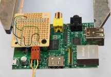
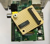
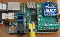
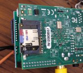
some fun pics from my rpi experiments today.
a small composite display, an xbee 'shield' and an adafruit half-length micro-sd card adapter.
system is now overclocked to 1ghz with the latest update.
a small composite display, an xbee 'shield' and an adafruit half-length micro-sd card adapter.
system is now overclocked to 1ghz with the latest update.
Attachments

you could also consider the DOGM lcd display modules; they have an i2c mode and you could (with some effort) get hitachi style lcd i/o working with the pi's i2c GPIO pins.
Hi Koon!...I want to supply MCLK (bit clock) from outside.
When I want to process 176.4kHz,
45.158MHz xtal -> as Master Clock, for DAC
45.158MHz -> HC163 counter -> 1/4 output = 11.2896MHz -> into PCM_CLK input, and Serial Clock, for DAC
So there will be multiplexer (1) = 45MHz/48MHz selection, multiplexer (2) = master clock and bit clock selection from counter output.
Any news about this? I'm crossing my fingers you succeed.
Hi,
No, I'm blatently taking inspiration from here Jeremy's Blog: Raspberry Pi with TextStar Serial LCD Display
So, just treating the LCD as a serial port, using python to make system calls to mpc, parsing the text from mpc status, formatting and writing to the serial port.
Unfortunately, the LCD is a bit small, but will suffice for now.
I intend to have some buttons attached to GPIO pins, which would then prompt the python code to call mpc to skip track etc (as well as have remote access to mpd).
fixed your link for you..
Hi Koon!
Any news about this? I'm crossing my fingers you succeed.
Hi I'm waiting Rev 2 board available. Allied Electronics shows "more than 12 weeks" and not specify revision.
So far I bought ODROID-X to try NEON SIMD engine for FIR processing.
Hi All,
Admittedly, I am in the UK, but I received a rev 2 (512Mb 'n' all!) within a week.
(If it's any consolation, I got up at the crack of dawn on the release day to register interest, before the farnell website crashed, and then had to wait 4 months for my first pi).
So the rev 2 boards, with the I2S pinout are out there, if you're waiting.
(thanks MrSlim for fixing my link)
Now need to solder a header for the I2S and play with registers...
I ordered a rev 2 last week, should have it sometime in November.. Looking forward to tinkering with this thing. I too will have to wire up the I2S port..
Well, taking the code from the above thread, and a few tweaks, I can see the I2S lines wiggling on my scope on P5 (not a very happy scope these days, so can't really analyse them properly).
I had to change the code to assign alt2 to gpios 28-31, and tweaked the clock divider settings to the suggestion in the thread for 44100kHz. Biggest issue I had was the the PCM_FS was constant. After a bit of fiddling and reading the datasheet, I discovered that you have to set a value for FSLEN (frame sync length) - it was previously set to 0 - which essentially disables PCM_FS.
So I have all three lines wiggling. Only outputting A0A0A0A0, and no idea if a DAC could work with it in it's current state, so I'll have to have a look on a working scope, and more tweaking. Would be nice to feed my TDA1541A with it as a next step.
After a lot of fiddling, I needed to increase the frame size to 64 bits, and the frame sync to 32 bits, and a halving of the clock divider to compensate (which doesn't seem right, a bit too quick), but I have audio out of my TDA1541A!
It's not using DMA or interrupts, 100% CPU, so you keep hearing the occassional glitch, but it already sounds much better than the PWM analogue output.
I'll post the code with my changes, probably to the rpi thread first, when it's working a bit better.
But, promising so far...
It's not using DMA or interrupts, 100% CPU, so you keep hearing the occassional glitch, but it already sounds much better than the PWM analogue output.
I'll post the code with my changes, probably to the rpi thread first, when it's working a bit better.
But, promising so far...
Excellent progress, I'm following closely - hopefully I will be able to take what you have done and put it to good use. (I'm not much for coding sadly..)
- Status
- Not open for further replies.
- Home
- Source & Line
- Digital Source
- Raspberry Pi -A New DIY'ers Digital Hub?