Yep.
And there is the school of thought that it's clipping, not a big amp, that blows most tweeters. Average power goes waaaay up during heavy clipping.
And there is the school of thought that it's clipping, not a big amp, that blows most tweeters. Average power goes waaaay up during heavy clipping.
Depends on the starting spectrum. Sine wave clipped adds HF. Pink noise clipped is still pink noise!
David S.
David S.
Yes, that's a nice succinct way of saying what I said in my long ramble.Hi DBM...,
I see what you are getting at. You are saying that if I(t) is the input signal and L(t), M(t) and H(t) and the low, mid and high passed filter components of I such that I(t) = L(t) + M(t) + H(t), then either L, M or H may have peaks of the same magnitude as peaks in I. Thus the amp for the HP, MP and LP sections must have the same voltage swing as that required for I alone.
I can buy that.
I agree with that.In reality I am of the school that follows lots of god clean power never hurts. If you blow a drivers by doing so then it just because you are trying to play the system louder than it is capable of.
I'm also of the school of thought that the best way to protect speakers against damage is to design them to be big and tough enough that they can play much louder than you can tolerate in the size of room they're intended for without suffering distress. 😀
If you have a small system that can only just reach your desired loudest playback level at their limits, you're always one slip of the volume control away from disaster. If the system can play comfortably louder than you can stand in the room you the listener become the protection system for the speaker...
Technically you might have enough amplifier power turned right up to damage them but you would be jumping out of your seat to reach for the volume control well before they ever got to a level to cause them any harm...
Which makes things even worse for the poor tweeter.Sine wave clipped adds HF.
Don't you get DC from clipping?Which makes things even worse for the poor tweeter.
Don't you get DC from clipping?
Only from single sided clipping. If you assume an input signal is fairly symmetrical and clips on both sides then you shouldn't get DC from it.
On the other hand, if you distort with even harmonics, say lots of 2nd harmonic, you create some DC or LF content.
David S.
It has been argued that due to high look back impedance, passive crossovers destroy driver damping and as a result there can be ringing around the driver's resonance, this being particularly bad for tweeters. I have always questioned that from the point of view that is the acoustic output of such a tweeter has a true 2nd order HP response, then it must have the transient behavior of an LR2 HP.
Hello John k…
This type of behavior came to my attention recently when I was experimenting with adding a conjugate impedance network to flatten a woofer’s impedance curve(both motional impedance peak and Le rise). Driven with a low Z amplifier, the LF response was the same with or without the conjugate network in parallel with the VC. No surprises there. And with the conjugate network in place , I could switch to a high Z amplifier and the LF response was identical to that produced by the low Z amplifier. In fact I added an additional 100 ohm resistance in series and still the LF response was the same, although lower in level. The reason for this is that with the conjugate network in place, the amplitude/phase response of the voltage applied to the woofer VC is the same no matter how much resistance is put in series between the amplifier and woofer.
You hit the nail on the head in the conclusion of your driver impedance analysis:
“The important thing to recognize here is that there is a one to one correspondence between the driver’s motion and the current through the VC, hence a one to one correspondence between the between the driver motion and Va(voltage applied to VC). The driver's impedance never changes regardless of how it is connected to the amplifier although the impedance of the network between amp and driver may take on any form.”
One thing that puzzled me for a while was the idea that the damping which defined the woofer LF response was provided by the impedance the woofer sees looking back toward the amplifier. Pushing down on a woofer, releasing, and watching the motion it is easy to see the difference between when the VC terminals are shorted together, or not. With the conjugate network in place, the amount of apparent damping provided was somewhere in between these two extremes. So, one might conclude that the woofer response when driven be a high Z amplifier would be less damped even with the conjugate network in place. But this simply isn’t the case.
I believe the difference in behavior between the perceived lack of damping in the push test and the measured response showing no change in damping is the method by which force was applied to the woofer. One used an external force(my hand) the other used current through the voice coil. Thoughts?
hahaha does that mean somebody actually read my post about a simple dc step inject test using a scope?
NOt that it was spectacularly good an idea perhaps, but it would illustrate the ringing cycles and their decay. I guess you could do the same with a audio program, and produce a gated tone/function, recording the mVolts across a small known R, and across the speaker directly for volts, on a scope/pcscope.
I havent fully formed my opinion on the matter, or I havent enough knowledge, or think its slightly semantic.
I dont believe Qes(driver) changes, other than with Temp/magnet weakening/soft iron corrosion.
But maybe its the term Qes is misused?
A series R or network will effectively change Qts as a product of changing the effective seen resistance. seen by the AMP. True the driver does not change. we all know this. Of course Qes doesnt change, just as it doesnt change when the driver is placed in a sealed volume.
Now im no expert so most of the following is probably incorrect, but this is how I visualise it, Without being enough of a math genius to dissect the math as well as the rest of you 😀
Doesnt Qms change? due to the sealed volume? Either way, Fs moves up. eg We tune for Qb 0.7 from a free air Qts 0.33, then we have to impose a more and hence stiffer air piston, which raises Fs, (due to the change in Qms from the free air value?) Qes remains the same, but driver Qts becomes that of the box, ie Qb = Qts
This is where my problem is. any added external R, will change Qts/Qb, of a given loudspeaker system. Since most amps and most speakers, most music loving, non audiophiles dont concern themselves with the impedance, and since most speakers are designed for low Z amps and most amps are low Z, for most its a non issue.
Im also not sure a high impedance amplifier is good, OR that bad. ive had SS amps with output impedance of around an Ohm, and others with quoted impedance of 0.1-0.2 Ohms. I think in the main this was due to the former having output choke, and the latter being DC coupled. former BJT class AB and letter MOSFET class H.... the lesser bandwidth, slower ancient BJT, with the higher impedance just sounded more musical.
Ok so most here are audiophiles/DIY nuts. including myself. to me its simple.
If you have a trusty amp youre gonna be keeping forever, then its easy enough to try.
Its something to try if youre planning to make a amp and speaker system, and design the speakers for a higher Z amp.
At the end of the day, an output impedance is a gate Z, before we even deal with speaker wire Z and crossover Z. Resistance at the gate is still power loss, its totally ignored in anyone arguements.
Maybe it is worthwhile to compare gate dissipation between 2 devices with very different output Z.
Thats what id like to see.
I just think that perhaps far far FAR too much relevance is given to the whole subject of output impedance.
Last edited:
The original test you propose was disclosed in a very old paper by Electro-Voice (reprinted here : http://www.pearl-hifi.com/06_Lit_Archive/07_Misc_Downloads/Critical_LS_Damping.pdf). Warning, there are some misconceptions and one plain wrong statements in that paper, besides some good stuff (EDIT: IHMO, that is)hahaha does that mean somebody actually read my post about a simple dc step inject test using a scope?
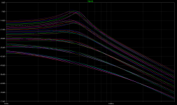
But a simple LTspice deck will do that test for you much easier. All you need is the voltage-refered cone displacment equation (for naked driver, or in IB/OB where Qms and Cms are in-situ parameters)
Xc(s) = Vs(s)*(BL/Re) / ( s^2*M + s*(1/Qms + BL^2/Re) + 1/Cms)
which can be used directly in this Laplace notation, then you can run both frequency and time-domain (fed with unit step) analysis on it.
It is a simple 2nd order lowpass and the effective Q and what contributes to it is readily apparent.
It will also give revealing insights of the effect of distortion when using combined stepping of Re (large steps), BL and Cms (small steps for these, also one can simplify it by changing Cms and BL in unison as they tend to do that in reality). Cms gets swamped out with higher damping.
See screenshot (frequency domain, the Re sets are offset vertically for visibility).
Attachments
Last edited:
Haha thanks KSTR, obviously I didnt invent this! It just struck me that it could produce some, perhaps even useful, data. And would be fairly simple to try. I didnt realise it was Laplace....oops. I guess I might be able to use that within a function block in something like MatLab then....hmmmmm
I havent read that paper, so thank you for posting it.
I still cannot see why power loss occurring in the output resistance of a 'highZ' amplifier, is better than the power loss occuring in a loudspeaker cable and 'lowZ' amplifier output, if the total Z are of equal magnitude.
surely all this does really, is cause a small volt drop, and also current limit, by loading the output stage down a little. hence reducing power. The problem is when L or C is added. as many have said, either way hiZ or loZ both have to meet transients of both V and I due to reactance.
Its a little like discussing whether to make a 2 stage amp to deliver enough current, when really the more current you get better. thats what has appealed to me with some MOSFET designs, their supposed high current capability. ive found many //BJTs to work well, beefing up o/p stages with extra pairs etc. all this stuff helps. but from what i know FETs in general dont do VAS too well. i think. So maybe then we make an amplifier, with some high bandwidth high voltage switching devices. step the voltage down using a valve OPT. Which would be better? Which would have the higher o/p impedance?
Or why arent there more push pull VC dual magnet front and back type woofers?
im no expert in that either though.
Last edited:
I think you guys are going around in a circle. I tried to address this before by making the distension between the driver and the system of which the driver is a part. When you put a driver in a box the the compliance of the system decreases. This leads to fc > fs, higher Qmc > Qms and Qec > Qes, and this system has a difference impedance than the driver as well.
ok. thanks.
so is the power lost in an output device 'better' power loss, than that lost in the speaker cables?
so is the power lost in an output device 'better' power loss, than that lost in the speaker cables?
I think you're getting confused between closed loop output impedance of an amplifier and the impedance of the actual output devices in the amplifier.Im also not sure a high impedance amplifier is good, OR that bad. ive had SS amps with output impedance of around an Ohm, and others with quoted impedance of 0.1-0.2 Ohms. I think in the main this was due to the former having output choke, and the latter being DC coupled. former BJT class AB and letter MOSFET class H.... the lesser bandwidth, slower ancient BJT, with the higher impedance just sounded more musical.
Ok so most here are audiophiles/DIY nuts. including myself. to me its simple.
If you have a trusty amp youre gonna be keeping forever, then its easy enough to try.
Its something to try if youre planning to make a amp and speaker system, and design the speakers for a higher Z amp.
At the end of the day, an output impedance is a gate Z, before we even deal with speaker wire Z and crossover Z. Resistance at the gate is still power loss, its totally ignored in anyone arguements.
Maybe it is worthwhile to compare gate dissipation between 2 devices with very different output Z.
Thats what id like to see.
In a solid state amplifier where the output impedance is, say, 0.2 ohms, this does not mean the output devices have an impedance of this magnitude, and therefore have low losses. On the contrary.
The output devices in an amplifier have a relatively high series impedance at any given instant on the order of tens or hundreds of ohms, and their series impedance is constantly varying with both input signal and load impedance.
It's negative feedback which lowers the output impedance to this level. This can either be loop feedback around several stages, local degeneration, (emitter follower etc) or both...it doesn't really matter.
The point is the feedback varies the high series impedance of the conducting output device in just the right way to cause it's output voltage to be maintained despite variations in load impedance - and by ohms law this means the equivalent output impedance is low. The power losses in the output devices are not reduced due to the feedback.
of course. My error. In which case i assume the nfb attenuator feeding the previous stage, or its own input, has a role in the output z, thus less nfb and higher nfb loop z in // with the output terminals. Roughly speaking. Depending on shunt/series topolmgy etc.
Distortion vs. driving impedance
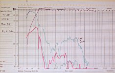
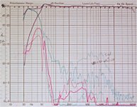
Here are the curves I have mentioned. They were done when I was at KEF on a 103.2 8" woofer bookshelf. The amplifier was an old Fisher 80AZ tube amp. The "AZ" part is a variable output impedance that uses a combination of voltage and current feedback to vary the output impedance for typically low to a measured 57 ohms.
The B&K oscilator had a feature called a compressor loop that allowed a measured voltage to be fed back and, within a wide range, it would vary its output to make that return path constant. This is done in a well filtered (slow) way, much like a hand on the volume control. This feedback was absolutely necessary because a 50+ ohm driving impedance would give a dramatically different frequency response than the usual low Z. Different response would mean different excursion and obviously distortion profiles that could not be fairly compared.
The curves are done with 90dB (at 1m) as the top line of the graph. That would also be the 100% distortion line. 20dB down would be 10% and the bottom of the graph is 0.3%. To make the 3rd harmonic distortion more visible I repeated that curve, from 60Hz up, with a 20dB increase. That would make the 20dB line the 0.3% level and the graph bottom 0.03%. Note that the green 3rd harmonic curve below 60 Hz is at the normal gain and approaches 100%.
Finally there are two black curves. The one that extends down to 25Hz is the total curve, that the compressor is keeping flat +-1dB, but rising at 12 dB per Octave from the lower left is the "fundamental only" curve, representing the maximum pure output. At mid frequencies where distortion is generally low they merge to become the same curve.
What you should see is that the curves are largely the same except fot the elevated green curves show significantly dropping 3rd harmonic output with higher drive Z. There is about a 10 dB drop as Z goes up. The LF distortion is generally unchanged. Interestingly the 2nd is strong but at very low frequencies the woofer is overdriven in both directions and distortion becomes largely 3rd (odd) order.
The other thing I mentioned was that each woofer had a 12dB per Octave LF assymptote of pure output. This pure output line was essentially independent of input leveland allowed easy comparison of relative woofer capibilities.
David S.
Attachments
Last edited:
Distortion vs. driving impedance
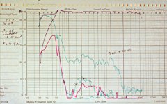
Thanks speaker dave for taking the time to post the distortion curves. Very interesting indeed.
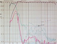
It appears that at LF the 3rd harmonic is essentially unchanged by source impedance.
The 2nd harmonic, however, is affected a bit at LF.
Increasing source resistance reduced 2nd harmonic below 30Hz, but increased it just above 30Hz.
Perhaps a byproduct of by overdriven?
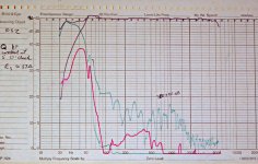
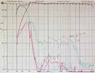
I created 3 visual overlays from your posted images so you can more quickly/easily see the differences in distortion products for the three different source impedances.
1) Low Impedance .vs. High Impedance
2) Low Impedance .vs. Medium Impedance
3) Medium Impedance .vs. High Impedance
Here are the curves I have mentioned. They were done when I was at KEF on a 103.2 8" woofer bookshelf. The amplifier was an old Fisher 80AZ tube amp. The "AZ" part is a variable output impedance that uses a combination of voltage and current feedback to vary the output impedance for typically low to a measured 57 ohms.
Thanks speaker dave for taking the time to post the distortion curves. Very interesting indeed.
It appears that at LF the 3rd harmonic is essentially unchanged by source impedance.
The 2nd harmonic, however, is affected a bit at LF.
Increasing source resistance reduced 2nd harmonic below 30Hz, but increased it just above 30Hz.
Perhaps a byproduct of by overdriven?
I created 3 visual overlays from your posted images so you can more quickly/easily see the differences in distortion products for the three different source impedances.
1) Low Impedance .vs. High Impedance
2) Low Impedance .vs. Medium Impedance
3) Medium Impedance .vs. High Impedance
Attachments
Last edited:
It appears that at LF the 3rd harmonic is essentially unchanged by source impedance.
I must be reading the charts wrong. To me it looks like H3 is the thing affected most by the impedance change. No?
- Status
- Not open for further replies.
- Home
- Loudspeakers
- Multi-Way
- raising driver Qts - you can't tuna fish