Yes, please. I am looking for all the causes of this reduction of distorsion.
Yeah, my subs could use some extra LF linearity and I've got a lotta amp!
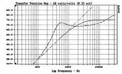
Is there feedback into the system from the driver's output? Because if there isn't, and you put lots of power in, you'll get power compression (which is reduced/eliminated with current drive), which was my meaning.Not really. The curves are taken at a fixed level of 80, then 90 dB at 1m. This includes achieving 90 dB at 20 Hz, which ends up being all distortion, so we are well into serious nonlinearity. The interesting byproduct of using a compressor for flat output is that you can track the level of fundamental and see what the maximum pure tone output of a unit is.
It turns out that there is a maximum pure tone output (1st harmonic) and it doesn't matter what the input level is, the 1st harmonic output is fixed. Higher input increases odd harmonic distortion level but not the fundamental. In fact there becomes a 12dB/Octave asymptote that defines maximum fundamental output for all bass frequencies for a given woofer.
This means that any woofer could be defined by its maximum pure output at, say, 50Hz, and thereby compared to any other woofer with one number.
I'll scan the curves this weekend.
Regards,
David S.
Is there feedback into the system from the driver's output? Because if there isn't, and you put lots of power in, you'll get power compression (which is reduced/eliminated with current drive), which was my meaning.
There was feedback in that a compressor loop held output constant. That was how I could make a fair comparison between low impedance drive and high impedance drive without having totally different response curves skewing the results.
David S.
Is there feedback into the system from the driver's output? Because if there isn't, and you put lots of power in, you'll get power compression (which is reduced/eliminated with current drive), which was my meaning.
Power compression is not distortion, it's a loss in sensitivity from voice coil heating leading to an increase in Re, just like a series resistance. This will change the frequency response somewhat, too, but again that is not distortion. Current drive will increase power delivery to maintain SPL at a more or less constant level, but again this is not fixing distortion, it's more akin to level matching. With that said, I am looking forward to more technical discussions and data on output impedance versus distortion at normal power levels.
Using a compressor to overdrive the excursion of the voice coil is a different thing alltogether.
-Charlie
No? Isn't that linear distortion?Power compression is not distortion, it's a loss in sensitivity from voice coil heating leading to an increase in Re, just like a series resistance. This will change the frequency response somewhat, too, but again that is not distortion.
-Charlie
EDIT: Hm, maybe not. I wonder if power compression affects all frequencies equally.
Last edited:
I wonder if power compression affects all frequencies equally.
The resistivity of Copper changes with temperature by about 0.4%/degree Centigrade. Power compression simply raises the DCR of the voice coil. Its effect looks identical to adding some resistance in series. In that regard it has the most effect where driver impedance is low and least effect at resonance and higher frequencies where impedance is higher and the percentage change is less.
Regards,
David S.
Rather than type in a long post here and not being able to edit it in the future, I generated a web page with my analysis of driver impedance. While I have not yet work through it, the analysis lead me to another observation concerning so called look back impedance and its roll in passive crossovers. It has been argued that due to high look back impedance, passive crossovers destroy driver damping and as a result there can be ringing around the driver's resonance, this being particularly bad for tweeters. I have always questioned that from the point of view that is the acoustic output of such a tweeter has a true 2nd order HP response, like and LR2 HP, then it must have the transient behavior of an LR2 HP. It should not matter whether this is obtained using an active crossover before the amp with direct connection to the amplifier, or through a passive crossover. I'll eventually have more discussion on this at my web site. For now, the analysis of the driver impedance can be found here.
It has been argued that due to high look back impedance, passive crossovers destroy driver damping and as a result there can be ringing around the driver's resonance, this being particularly bad for tweeters. I have always questioned that from the point of view that is the acoustic output of such a tweeter has a true 2nd order HP response, like and LR2 HP, then it must have the transient behavior of an LR2 HP. It should not matter whether this is obtained using an active crossover before the amp with direct connection to the amplifier, or through a passive crossover.
Absolutely, if you can achieve an LR2 response with passive means then the transient response is the byproduct of that shape and has nothing to do with the means of achieving it.
I always get antsy when people start talking about amplifier damping as some way for the amplifier to "reach out and grab the cone", etc. etc. In the end it is just about the interaction between the output impedance and the impedance curve of the driver. The typical network topology allows driver voltage to swing high when impedance goes high.
The worst offender in this regard is the first order network since it is purely a series network with no shunting elements. Typically we want to crossover above the driver resonance so, by definition, the network is high impedance at the driver resonance point. (see attached figure for comparison of series capacitor network to first order ideal.)
You mention driver time constants and I can relate some measurements I took while at KEF working on the KM1 monitor. We did a lot of voice coil temperature measurements by injecting a small amount of current and measuring DCR. I did this with a B&K chart recorder that could be run at a wide range of chart speeds. The test was to feed in a large sine wave and watch the temperature rise to a new plateau. It would plot out as the typical exponential asymptotic rise and the time constant culd be pulled directly from the curve.
If I remember correctly most tweeter voice coils had time constants in the 2 to 5 second range. Woofers would be more in the 5 to 15 second range, since there was a larger mass of copper involved. Now if you ran the chart recorder much slower the voice coil time constant would be a quick blip, but there would be a slower time constant revealed, that of heating up the magnet structure. This might take a half an hour or so, again depending on the mass (thermal) of the magnet structure. For our protection circuit that depended on modeling, this was important too. If you had a long monitoring session , not only would the quick rises from short musical blasts be important, but the creaping up "ambient" that the voice coil resided in would be the constantly heating magnet structure.
Turning the chart recorder even slower would reveal an even longer time constant of heating up the whole system's cabinet. I suppose if we looked for it we could measure the outside room warming up as well?
Regards,
David S.
Attachments
...It has been argued that due to high look back impedance, passive crossovers destroy driver damping and as a result there can be ringing around the driver's resonance...
John, thanks for sharing that analysis with us.
I think that I can buy into the phenomenological argument that back EMF can be "shorted out" by a very low amplifier output impedance (assuming direct driver to amp connection) while any network in between that presents any non-zero impedance would generate a new voltage in the circuit. My assumption is that this would result in a new signal that could be considered "distortion" of some kind, and this is the basis for arguments against passive crossovers. What are your thoughts on this line of reasoning?
-Charlie
That type of argument is often sited by proponents of active crossovers. But it is not distortion, it is just a different transfer function which is easy enough to correct. It is true that if the driver is connected directly to a low impedance source then if the output of that source abruptly stops, say as following an impulse stimulus, the voltage across the driver is the full back emf where as if there is a significant "look back" impedance, as might be the case for a passive crossover, only a portion of the back emf will be across the driver. The problem with that argument is that with an active crossover, if the system is stimulated by an impulse (at the input of the active crossover), the output of the active crossover, hence the amplifier, will not abruptly stop after the impulse passes. The voltage at the amp's output will have a transient associated with transfer function of the crossover. Thus, even though the driver is directly connected to the amp, the voltage across the diver will still be only a fraction of the back emf. The point being that if the passive and active crossover have the same transfer function the decay of the voltage applied at the driver terminal, Va, following stimulus of the system by an impulse will be the same and the voltage across the VC will be Va - Vb in either case. The driver will response the same.
The point is that what controls the driver is not the back EMF but the voltage across the driver. How the "system" is designed to generate that voltage is irrelevant. In fact there is another way to look at this. Any current generated by the back EMF opposes driver motion. Thus, the amplifier must supply sufficient current to overcome this opposing force. So which way does the amplifier have better control, when the force opposing motion is at a max or when it is reduced?
That doesn't mean that active don't have some possible advantages over passives. Such potential advantages might include lower insertion losses and different response to voice coil heating, and greater efficiency since no power is dissipated in the crossover. The possible disadvantages are the need for multiple power amplifiers, more interconnect and additional speaker cables.
This is a story with many sides and angles and there is no one way being better than another.
Greater efficiency is one of the main rallying cries of those who advocate active crossovers - the claim is that by eliminating the insertion loss of a passive network (both unwanted losses in inductors and capacitors, as well as required losses like L-Pad's to match driver sensitivity) that an active system with multiple amplifiers and no passive L-Pads or crossovers must be more efficient.That doesn't mean that active don't have some possible advantages over passives. Such potential advantages might include lower insertion losses and different response to voice coil heating, and greater efficiency since no power is dissipated in the crossover. The possible disadvantages are the need for multiple power amplifiers, more interconnect and additional speaker cables.
Well it can be, at full output but as a whole system, not at a normal playback level, nor while idle. Why ? Because most of the power use of an amplifier tends to be the bias induced idle dissipation overhead which is a lot higher than most people realise.
A typical 100 watt capable (into 8 ohm) class AB power amp will have an idle dissipation somewhere between 5 and 20 watts per channel, with 15 watts being typical.
In a stereo amp that's 30 watts going up in heat in the output stages whether you're playing music or not. Now multiply that by 3 for a fully active 3 way stereo speaker system and you have 6 channels x 15 watts = 90 watts of continuous amplifier dissipation before you even play any music.
When you consider that the average power level for playback on a pair of 90dB/w/m + speakers is only a few watts, that's a huge waste of power and hence a poor overall system efficiency, if you measure it right back to the mains cord of the amplifier.
Some people might be tempted to say "but you don't need a 100w amplifier for the tweeter as a tweeter can only dissipate a few watts, using a smaller power amp for the tweeter channels will reduce idle dissipation".
Well yes, a tweeter only dissipates on average a few watts, but the instantaneous transients fed to a tweeter can still be very high, approaching 10x the average power. That means you still need an amplifier channel capable of enough voltage swing that would represent 100 watts into 8 ohms to avoid clipping on peaks, even though the average power delivered to the tweeter might be 5-10 watts. That means an amplifier with a high idle dissipation.
If you have an amplifier capable of the voltage swing for 100 watts into 8 ohms for the passive design you, you need 3 such amplifiers capable of 100 watts into 8 ohms in the active design, so that the individual drivers still have the same headroom before clipping. (If the mid and tweeter had 3dB of attenuation technically those two amplifiers could be rated for 50 watts but that's not much of a gain)
If you only have a modest amount of driver attenuation in a passive design (say no more than 3dB) then in terms of total input power to the amplifier and total amount of waste heat into the room, the passive design with 2 amplifier channels is almost always going to use less power overall than 6 channels worth of amplifier driving a pair of active 3 ways...certainly at anything less than maximum volume.
Active designs have some advantages, but whilst an active speaker might technically be more efficient, there is far more power wastage in the overall system than the passive design due to the additional amplifier channels, especially if the amplifier is left powered up and idle a lot.
(It's also a sobering thought for those of who use 5+ channel AV receivers almost entirely in stereo mode - unless the amplifier actually powers down the unused channels in stereo mode, which many don't, you're looking at 80+ watts of idle dissipation...)
Last edited:
If you have an amplifier capable of the voltage swing for 100 watts into 8 ohms for the passive design you, you need 3 such amplifiers capable of 100 watts into 8 ohms in the active design, so that the individual drivers still have the same headroom before clipping.
Yes and no. If each driver in a system is capable of handling an X volt peak, then for the active system 3 amps of power X^2/8/2 into 8 ohms would be required. For the passive system, assuming no insertion losses, the amp would need to be able to provide a peak voltage of 3X or a power 9 times that of the amps used in the active system to assure it could produce the same SPL level as the active system without clipping.
The power comparison can be confusing and there are several ways to look at it. One way that isn't right is any notion like "I had 150 watts into a passive system and that would be equivalent to a triamped system with 3 x 50 watts". The distribution of power will just not be that tidy. At some points in time the peak spectrum might be fully in a single driver's passband. That being the case the only way an active system can be guaranteed the same peak output as the 150 watt passive system is with 3 x 150 watts driving it.
A factor that must be considered is the passive network loss from frequency shaping. We had an early bi-amped monitor system at KEF the BBC LS5 1ac, that used a fairly mediocre 50 watt amplifier. In the end the output capibilities where quite high and it was due to the strongly climbing raw response of the 12" woofer. That was free midrange efficiency that would have to be thrown away in flattening the response with a passive network.
Based on this I developed a broadcast monitor, the P60, that had a passive network with driver blending but no response shaping. This allowed 3-4 dB greater mid frequency sensitivity. EQ in the amp flattened the response. This predated the KEF Kube EQ and bass extension boxes.
The ideal case would be if the basic sensitivity curve of the system could follow the peak spectral contour of music, and active EQ would then flatten the system with no efficiency loss.
David S.
Why would it have to supply 3X? I don't understand. How has the headroom changed?
Assume for the purpose of example that 3 drivers of a 3-way are all 8 ohm (for simplicity of calculation). Also assume that all three drivers have a max RMS power rating of W watts. W watts into 8 ohms would require a voltage of V = sqrt (8W) across the drivers. An active system would require 3 such amps. A single amp would also have to be able to supply a signal of V volts across each driver at the same time. Since this is coming from a single amp, the three voltages sum and you have to allow for the possibility that they will sum in phase. Thus the single amp must be capable of a voltage output of 3V. Since power is W = (V^2/R) this becomes 9V^2/8 for the single amp compared to V^2/8 for the single amp.
The passive crossover would divide the signal back into 3 separate signals of amplitude V and the power delivered into each driver would still be the same. But is is the voltage requirement that is the hangup.
For example, suppose the speaker has crossover points of 300 and 3k Hz and the input to the speaker is a signal consisting of a 100Hz tone + a 1k Hz tone + a 10K Hz tone. Then the signal is V(100) + V(1k Hz) + V(10K Hz) which will have a maximum of 3V when all three components are simultaneously in phase. The passive crossover will separate that back to 3 separate wave forms of amplitude V. An active crossover will separate the signal before the amp hence each amp of the active system will only need to deliver an output of V volts.
I hope this helps you understand why the voltage capability of the single amp must be 3 time that of the individual amps.
Of course, one of the dangers of the single amp/passive system is, as Dave points out, that it could also deliver a signal with amplitude 3V into a single driver which would likely fry the driver. So the active system has the added advantage that there is some additional protection for the individual drivers since the amps can be sized specifically for the maximum capability of each driver rather that based on the total system needs. Thus the only way a passive system can be guaranteed to have the same broad spectrum SPL capability of a correctly amplified active system is to use an amp which could potentially destroy any single driver in the system. 🙁
Last edited:
Yes and no. If each driver in a system is capable of handling an X volt peak, then for the active system 3 amps of power X^2/8/2 into 8 ohms would be required. For the passive system, assuming no insertion losses, the amp would need to be able to provide a peak voltage of 3X or a power 9 times that of the amps used in the active system to assure it could produce the same SPL level as the active system without clipping.
Dave has beaten me to it with his response, but what I wanted to say is that you're looking at the problem the wrong way around.
You cannot directly compare the voltage swing / power requirements of the single channel vs 3 channel divided spectrum case on a 1 for 1 basis, you can only compare the relative best case scenarios and worst case scenarios. The best case for the 3 channel arrangement is even spectral power distribution, the worst case is a single frequency falling in one band only.
If we take the single amplifier channel with passive crossover as the starting point then say how must we spec the individual amplifiers of a 3 way active crossover so that in the worst case scenario we have the same or better clipping headroom for each driver than the passive system, the correct answer is that (ignoring insertion loss of the passive networks) each individual amplifier must have the same potential maximum voltage swing, and therefore the same power rating into a given impedance load.
Your analysis is based on an optimistic best case scenario where power that was previously provided by a single amplifier is evenly distributed amongst the 3 separate bandwidth limited amplifiers.
Now, you could make an argument that typical music will on average have a spread out spectrum that is fairly evenly distributed, albeit biased towards the low end of the spectrum and away from the tweeters range, which will tend to work in favour of the multi-channel amp, just as it works in favour of a multi-way loudspeaker.
However we're not talking about average power distribution from the perspective of amplifier/driver heating, we're talking about headroom for peak transients, and there is nothing to say that typical musical transients will follow this same average spectral power distribution, in fact they will more than likely not.
Two major sources of high level transients are percussion bass (bass drums etc) and percussion treble (symbol hits etc) and both of these will tend to have their energy concentrated largely or entirely within one band of a 3 way system, which means the individual amplifiers require their full potential voltage swing to ensure no clipping on the same signal which would not have clipped in the single amplifier case.
If your analysis was taken at face value it would suggest that three 11 watt amplifiers would have sufficient voltage swing to replace one 100 watt amplifier, however this would only ever be the case on a signal like pink noise, never on narrow bandwidth transients, nor music.
Yes excellent point, I was thinking about that but didn't mention it. The most efficient scenario of all is a hybrid one - do the frequency division passively to avoid having extra idling amplifier channels wasting power, but do most of the response shaping, baffle step correction in particular actively, so you're not throwing away (potentially) 6dB of power in the midrange and treble.A factor that must be considered is the passive network loss from frequency shaping. We had an early bi-amped monitor system at KEF the BBC LS5 1ac, that used a fairly mediocre 50 watt amplifier. In the end the output capibilities where quite high and it was due to the strongly climbing raw response of the 12" woofer. That was free midrange efficiency that would have to be thrown away in flattening the response with a passive network.
Based on this I developed a broadcast monitor, the P60, that had a passive network with driver blending but no response shaping. This allowed 3-4 dB greater mid frequency sensitivity. EQ in the amp flattened the response. This predated the KEF Kube EQ and bass extension boxes.
The ideal case would be if the basic sensitivity curve of the system could follow the peak spectral contour of music, and active EQ would then flatten the system with no efficiency loss.
David S.
That's exactly what my current system does - the crossover is passive, and because the two drivers happen to have matched sensitivity at the crossover point I don't even have an L-Pad on the tweeter.
All the baffle step correction and some overall response shaping is done actively at line level, so no power is wasted through passive baffle step correction, there is just a small insertion loss due to inductor resistance.
I think my original point still stands though - even with 6dB of passive baffle step correction in a passive design, the wasted power is on average still going to be less than the idling power of the two extra amplifier channels in the active crossover design.
If your average playback level works out to about 5 watts (with transient peaks maybe reaching 50 watts) with an average midrange+treble power level of say 2.5 watts, and you're throwing away 3/4 of your midrange and treble power with 6dB baffle step correction, your "wasteful" passive baffle step correction is wasting about 1.9 watts on average in heating the room. Meanwhile the two additional amplifier channels in the active crossover system are probably idling at 15x2 = 30 watts.
Fully active will start to gain ground on systems like PA and club sound systems where they are running flat out most of the time making the idle power of the amplifier a smaller proportion of the total, but for home listening I really don't think that's the case.
Last edited:
Hi DBM...,
I see what you are getting at. You are saying that if I(t) is the input signal and L(t), M(t) and H(t) and the low, mid and high passed filter components of I such that I(t) = L(t) + M(t) + H(t), then either L, M or H may have peaks of the same magnitude as peaks in I. Thus the amp for the HP, MP and LP sections must have the same voltage swing as that required for I alone.
I can buy that.
Thanks John for your detailed response. I see what you're driving at - please pardon the pun. And your post above in reply to Simon is also how I see it. See my last paragraph below.
I see this in terms of headroom. My example follows:
My average level is 1V RMS or 85dB at the listening position. If the program material is decently mastered that average level will be 18dB below full scale, meaning that I want a clean 8V on the peaks. Wherever that peak is, 50Hz, 500Hz, 5Khz, 8V is what I need. So in a three way system with drivers of equal sensitivity, I need an amp that can deliver at least 8V peak (5.7V RMS).
It doesn't matter if that comes from 1 amp or 3. Of course in a 3 amp system each amp will have an average load a lot less than a single amp into a passive system. But to hit the peaks, each amp still needs to supply 8V peak. Admittedly, those 8V peaks will be rare at the top end of the spectrum.
In practice of course, you can get away with a smaller amp on parts of the system. My horns are about 10dB/watt more sensitive than the woofers. If running active then the horn can hit its peaks with 1V or less. Don't need much of an amp for that. And if you don't mind clipping the occasional high frequency peak, even less voltage is needed.
FWIW, the equal energy dividing point is about 635Hz for pink noise. If a two way system were divided there (I've done it) then each amp would be pushing the same amount of power. That point does change tho, depending on musical style. I find it to be about 500Hz for the Blues.
For proper headroom, each amp needs to supply the same peak value, if the drivers have matched sensitivity. Those peak values may be rare at the top of the musical spectrum, but if you don't want to clip them, then you need the headroom.
I think both ways are reasonable ways to look at the problem. My first way was based on the max power requirements of each driver. The second is based on being able to supply the peak voltage of the output signal to any of the driver's in the system. Another way to do it in the active case is to limit the amplifier power (or voltage) so that the drivers can not be pushed past their respective excursion limits.
In reality I am of the school that follows lots of god clean power never hurts. If you blow a drivers by doing so then it just because you are trying to play the system louder than it is capable of.
In reality I am of the school that follows lots of god clean power never hurts. If you blow a drivers by doing so then it just because you are trying to play the system louder than it is capable of.
- Status
- Not open for further replies.
- Home
- Loudspeakers
- Multi-Way
- raising driver Qts - you can't tuna fish