Which resistors to use ?
Any suggestions on the lower limit for the power rating (watts) of the series resistor ? I have tried a cheap wire-wound alu-clad 5w 6.8ohm, and it's remains cold and seem to work well. So I was thinking of building a diy 4 pole stepped attenuator with my choice of resistors in place. This would allow me to adjust the high/low frequency responce to taste. My speaker are all fullrange - nothing too high powered.
I was wondering if the switching of the stepped attenuator would cause any damage to the speaker/ solid state amp ?
eBay - The UK's Online Marketplace
I'm not sure what is ment by 'rotary is made before break' . 24 steps seems a little excessive but I figured I could leave some blank.
For the resistors I was thinking of using KOA/kiwame 2w /5w. Maybe try a few audionote tantalums in few positions. 2w would be smaller and more cost efficient but I'm concerned about heat and sound quality.
Any thoughts ?
Dave
For the resistors I was thinking of using KOA/kiwame 2w /5w. Maybe try a few audionote tantalums in few positions. 2w would be smaller and more cost efficient but I'm concerned about heat and sound quality.
Any thoughts ?
Dave
Do non-polarised tantalum caps exist? I didnt think they did, so excuse me if i am mistaken.
seriously? 2w or 5w resistors? Id go for at least 10watts no matter how low powered your system may be.
Strange nobody mentioned the influence of the airload modifying the systemparameters.
For instance, Qesbg (the resonant systems electrical damping by the motor) depending on the enclosure will be:
Qesbg = Qes/mb x (1 + Rg/Re)
mb for a fully stuffed closed box is around 0,9
mb for a bassreflex with somedamping is around 0,94
Rg = generator resistans including all possible driver external resistanses
Re = driver dc resistans
goes without saying that also fs, Qms and sensitivity will be notable affected by the airload
also worth mention may be that by putting a compressinchamber in front of a woofer (amongst other things) the systems Q can be raised and fres can be lowered (offcourse only at the expense of senisitivitie)
I did today a THD measurement with first a PSE tube amplifier without feedback and second with a hypex class-d amp. It has higher second harmonic but the third harmonic shows almost similar level as the class-d amp!Here are the curves I have mentioned. They were done when I was at KEF on a 103.2 8" woofer bookshelf. The amplifier was an old Fisher 80AZ tube amp. The "AZ" part is a variable output impedance that uses a combination of voltage and current feedback to vary the output impedance for typically low to a measured 57 ohms.
The B&K oscilator had a feature called a compressor loop that allowed a measured voltage to be fed back and, within a wide range, it would vary its output to make that return path constant. This is done in a well filtered (slow) way, much like a hand on the volume control. This feedback was absolutely necessary because a 50+ ohm driving impedance would give a dramatically different frequency response than the usual low Z. Different response would mean different excursion and obviously distortion profiles that could not be fairly compared.
The curves are done with 90dB (at 1m) as the top line of the graph. That would also be the 100% distortion line. 20dB down would be 10% and the bottom of the graph is 0.3%. To make the 3rd harmonic distortion more visible I repeated that curve, from 60Hz up, with a 20dB increase. That would make the 20dB line the 0.3% level and the graph bottom 0.03%. Note that the green 3rd harmonic curve below 60 Hz is at the normal gain and approaches 100%.
Finally there are two black curves. The one that extends down to 25Hz is the total curve, that the compressor is keeping flat +-1dB, but rising at 12 dB per Octave from the lower left is the "fundamental only" curve, representing the maximum pure output. At mid frequencies where distortion is generally low they merge to become the same curve.
What you should see is that the curves are largely the same except fot the elevated green curves show significantly dropping 3rd harmonic output with higher drive Z. There is about a 10 dB drop as Z goes up. The LF distortion is generally unchanged. Interestingly the 2nd is strong but at very low frequencies the woofer is overdriven in both directions and distortion becomes largely 3rd (odd) order.
The other thing I mentioned was that each woofer had a 12dB per Octave LF assymptote of pure output. This pure output line was essentially independent of input leveland allowed easy comparison of relative woofer capibilities.
David S.
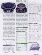
The picture shows the response of a two way mid-high section using a high quality mid off PHL-audio and a super tweeter horn.
An externally hosted image should be here but it was not working when we last tested it.
Last edited:
I have to say the tube amplifier sounds better to my ears in direct comparison to the class-D amplifier. Although the THD is higher.
I did today a THD measurement with first a PSE tube amplifier without feedback and second with a hypex class-d amp. It has higher second harmonic but the third harmonic shows almost similar level as the class-d amp!
Hi Helmuth,
Interesting curves but a bit confusing to me as you are showing a increase in second harmonic where my curves showed an increase in third. I believe I was showing the distortion inherent in a ferrite magnet structure. Is yours perhaps the 2nd harmonic of a single ended output circuit? (but why then not a smooth function?)
Any ideas?
David
Ps, how did you maintain the same response and what was the tube amp output impedance?
What you see in my graphic is the distortion of speaker and amplifier at 2.9V. The amplifiers have both low distortion at 2,8V although I never measured the distortion of the tube amplifier. The distortion of the UCD180 at 2,9V is 0,0035% in the spec. The distortion of the tube amplifier is not compensated in the measurement.Hi Helmuth,
Interesting curves but a bit confusing to me as you are showing a increase in second harmonic where my curves showed an increase in third. I believe I was showing the distortion inherent in a ferrite magnet structure. Is yours perhaps the 2nd harmonic of a single ended output circuit? (but why then not a smooth function?)
Any ideas?
David
Ps, how did you maintain the same response and what was the tube amp output impedance?
The tube amp had some variation I use my oscilloscope to set on 2,9V but with tube amp I did see 2,7V and also 3V due the impedance variation of the speaker. The horn tweeter has a near flat impedance due the attenuation.
But it is the real measurement fist on the PSE tube amp and second measurement on the class-D amplifier.
I did not measure the output impedance of my tube amplifier will be some where between 5-8 Ohm.
Conclusion of this measurement is that the tube amp has the high second harmonic or the poor damping factor of the tube amp increases the second harmonic.
I was hoping to see a decrease of the third due the poor damping/ higher output impedance of de PSE tube amp.
Last edited:
- Status
- Not open for further replies.
- Home
- Loudspeakers
- Multi-Way
- raising driver Qts - you can't tuna fish