I just built a se amp with these tubes,BUT I just realized that I designed the amp to run with EL 36,just found out that 6P31S only can stand 13w
and the EL36 about 15w,so I get a little just a little (hardly can se it)red glow.
Now the qeustion -> will this be a problem?
and the EL36 about 15w,so I get a little just a little (hardly can se it)red glow.
Now the qeustion -> will this be a problem?
... I get a little just a little (hardly can se it)red glow.
Now the qeustion -> will this be a problem?
What is your supply voltage and standing current ?
You have a problem. Red glowing anode indicates clear overload.
Yes,I know..You have a problem.
The voltage over the tube is 300v and the current is 60mA so it all end up to 18w.
I have CLCLC smothing so I will try to lower the first C..
I just ordered some caps.
IMO, the right way is use Kenotron like rectifier in PSU, that will decrease +U and will increase quality of sounding....
Last summer I made some SE output stage comparison with 6P31S, 6P13S and 6P41S.
With all these I used output transformer having 4k2 to 8 ohms impedance.
Optimum operating conditions for 6P31S was Ik = 65 mA, Ua = 250 V.
This is some 16 W, but I did not notice any sign of overload.
With these values the linearity was best i.e. THD was lowest.
By the way; with properly biased 6N9S as a voltage amplifier, one can get a very effective distortion cancelling.
This combination will halve the THD compared with 6P31S only.
I think I will draw this schematic. Now it is only in my notebook.
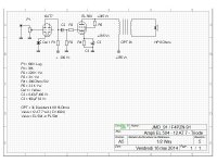
Done. This is the optimum circuit (as per my measurements...):
https://www.dropbox.com/s/33njq0opf453kfw/6P31S_6N9S_SE.GIF?dl=0
As an example about the distortion cancelling, when Pout = 3 W, THD at the output is 0,7 %, but at the grid of 6P31S THD is some 2 %.
Sensitivity for 3W out is some 600 mV in.
An externally hosted image should be here but it was not working when we last tested it.
https://www.dropbox.com/s/33njq0opf453kfw/6P31S_6N9S_SE.GIF?dl=0
As an example about the distortion cancelling, when Pout = 3 W, THD at the output is 0,7 %, but at the grid of 6P31S THD is some 2 %.
Sensitivity for 3W out is some 600 mV in.
Last edited:
Artosalo,thanks for the schema.
I use 6e6p as drivertube with CCS (30mA) on the B+
I have not messaured the distortion,but it sounds good! 🙂
I use 6e6p as drivertube with CCS (30mA) on the B+
I have not messaured the distortion,but it sounds good! 🙂
Theres no space on the chassie,unless theres a 9 pin mini of the Kenotron,is there?IMO, the right way is use Kenotron like rectifier in PSU, that will decrease +U and will increase quality of sounding....
I will first try to change the elyts,If that don´t work I will use the EZ81.
As I only have single winding,can I use this one?:

As I only have single winding,can I use this one?:
Out of curiosity I wonder why it's considered bad to exceed Pmax and get the anode hot ie what would be the nature of harm?
Let's say the anode temperature, perhaps also g2 is too hot so that it glows faintly. I suppose 4 potentially harmful effects, none of which might happen in practice: 1) anode/g2 metal softens and droops, prob more of a g2 issue - but for the anode in practice seems to remain formed to shape IME when I've overcooked it accidentally on numerous occasions 2) Metal outgas impurities/ions, which might or might not happen and might or might not be taken care of by the getter - maybe all the action on outgassing happens quite quickly and longer term there's then nothing left to 'outgas', ie it's already gone. 3) indirect heating of g3/g1 ? Not a problem unless mechanical droop, and I'm just guessing it might be an issue though never heard of it 4) Glass envelope gets hot - might eat into thermal spec limit so depends on environment I suppose.
Does this seem so bad ? Thoughts ?
Without going deeply into the process what happens inside the overloaded and red glowing tube, isn't that obvious that the lifetime of such tube is essentially shortened.
Sometimes a little overheating over time can lead to more serious consequences including plate outgassing, secondary emission from the plate to the screen, deformation of the plate structure, melting the screen grid as the plate overheats due to increased screen current due to secondary emission or gas, ion bombardment of the cathode, all of which can result in catastrophic failure, and at an extreme burning a hole through the plate and possibly softening the glass envelope to the point where it lets the air in..
George from Tubelab can elaborate considerably on the possible outcomes some of which can be spectacularly entertaining.
The least extreme would be greatly shortened tube life, the most - well just let your imagination run wild and then search for some of tubelab's posts on related subjects.
George from Tubelab can elaborate considerably on the possible outcomes some of which can be spectacularly entertaining.
The least extreme would be greatly shortened tube life, the most - well just let your imagination run wild and then search for some of tubelab's posts on related subjects.
Well not to me it isn't obvious ! Physically, the anode and perhaps g2 are hotter than intended, that's a fact. But by what mechanism that might then translate to reduced life provokes my curiosity. As I posted above, I could think of 4 possible reasons, none of which might actually happen in practice or not a significant extent.....Without going deeply into the process what happens inside the overloaded and red glowing tube, isn't that obvious that the lifetime of such tube is essentially shortened.
I don't mean so hot as be incandescent or cause mechanical changes ! For discussion purposes lets say showing early signs of starting to glow faintly.
@Kevinr AFAIK outgassing from the anode (perhaps g2) is the main cited reason for reduced lifespan following overtemperature. But I'd venture that can only happen once, and quite quickly if at all - ie degradation would be rapid and show up in characteristics one might think - but IME it doesn't ? And yup, tubelabs stuff is hugely entertaining and intriguing IMO !
I'm only mooting intentional overtemperature as an armchair discussion. A valve like an EL36 would seem a lot more 'appliable' if it would tolerate say 20W or 25W anode diss IMO. Small signal valves have higher gm at high Ik too, for example. I'm not advocating, just curious.
Last edited:
Hi JM - yes that seems a good discussion example. I don't know the EL/PL504 triode curves that well, and published curves run out for va=Vg2 =190V AFAIK. But guesstimating that you end up with about -28V bias and so Pa+Pg2 about 21W. Versus design centre spec max 17W. But actually Design Max is 24W, so perhaps that anode doesn't even begin to glow ? I don't wish to seem like tubelabs, but could you sensibly go further I wonder ?
Hi JM - yes that seems a good discussion example. I don't know the EL/PL504 triode curves that well, and published curves run out for va=Vg2 =190V AFAIK. But guesstimating that you end up with about -28V bias and so Pa+Pg2 about 21W. Versus design centre spec max 17W. But actually Design Max is 24W, so perhaps that anode doesn't even begin to glow ? I don't wish to seem like tubelabs, but could you sensibly go further I wonder ?
hello ,
i not problèm to risk dead the valve EL / PL 504 ... the OPT is 3 K / 8 Ohms , i tested other valve ... EL 502 !
so good performance and current to cathode is 115 mA in EL 502 vs 100 mA to EL 504 .
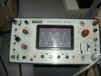
i joint the graphic to EL 504 , little distortion 🙁
the futur build is UL , so happy build to mixer Triode / Penthode .
😉
Attachments
- Home
- Amplifiers
- Tubes / Valves
- Question about 6P31S